Approved by
Approved by
Order of the Federal
Environmental, Industrial
and Nuclear Supervision Service
dated 7 December 2015 No. 502
FEDERAL RULES AND REGULATIONS
IN THE FIELD OF ATOMIC ENERGY USE "RULES FOR CONTROL
OF BASE METAL, WELDED JOINTS AND DEPOSITED
SURFACES DURING OPERATION OF EQUIPMENT, PIPELINES
AND OTHER COMPONENTS OF NUCLEAR POWER PLANTS"
(NP-084-15)
I. Purpose and scope
1. These federal rules and regulations in the field of atomic energy use "Rules for control of base metal, welded joints and deposited surfaces during operation of equipment, pipelines and other elements of nuclear power plants" (hereinafter referred to as the Rules) were developed in accordance with the Federal Law No. 170-FZ dated 21 November 1995 "On atomic energy use" (Collected Acts of the Russian Federation, 1995, N 48, art. 4552; 1997, N 7, art. 808; 2001, N 29, art. 2949; 2002, N 1, art. 2; N 13, art. 1180; 2003, N 46, art. 4436; 2004, N 35, art. 3607; 2006, N 52, art. 5498; 2007, N 7, art. 834; N 49, art. 6079; 2008, N 29, art. 3418; N 30, art. 3616; 2009, N 1, art. 17; N 52, art. 6450; 2011, N 29, art. 4281; N 30, art. 4590, art. 4596; N 45, art. 6333; N 48, art. 6732; N 49, art. 7025; 2012, N 26, art. 3446; 2013, N 27, art. 3451), Decree of the Government of the Russian Federation No. 1511 dated 1 December 1997 "On approval of the Regulation on development and approval of Federal rules and regulations in the field of atomic energy use" (Collected Acts of the Russian Federation, 1997, N 49, art. 5600; 1999, N 27, art. 3380; 2000, N 28, art. 2981; 2002, N 4, art. 325; N 44, art. 4392; 2003, N 40, art. 3899; 2005, N 23, art. 2278; 2006, N 50, art. 5346; 2007, N 14, art. 1692; N 46, art. 5583; 2008, N 15, art. 1549; 2012, N 51, art. 7203).
2. These Rules establish requirements for control of condition of base metal, welded joints and deposited surfaces (hereinafter referred to as metal) during operation of equipment, pipelines and other components of nuclear power plants. In these Rules, other NPP component is understood as equipment (including its subcomponents) and pipelines which is not covered by the federal rules and regulations in the field of atomic energy use specifying the requirements for design and safe operation of equipment and pipelines for nuclear power installations (hereinafter referred to as the Rules of design and safe operation).
The abbreviations used are presented in Appendix No. 1, terms and definitions used are presented in Appendix No. 2 hereto.
3. These Rules establish the procedure for assessment of compliance of metal of equipment, pipelines and other NPP components conducted by the operating organization in the form of control.
4. The state of metal of the following equipment shall be controlled during operation:
a) equipment and pipelines operating under excessive or vacuum pressure, which are subject to the Rules of design and safe operation;
b) equipment and pipelines (as well as turbine housings, valves, filters and pumps) <1>, operating under excessive or vacuum pressure and classified as elements of the third safety class, which are not subject to the Rules of design and safe operation;
c) supports and hangers, fasteners of equipment and pipelines specified in subparagraphs "a" and "b" <1> of this paragraph;
d) internals of reactors <1> of the VVER type (pit, protection tube unit, reflection shield - for VVER-1000 reactor facility; pit, bottom of the pit, protection tube unit, removable basket - for VVER-440 reactor facility);
e) metalworks of RBMK and EGP type reactors <1>;
f) metalworks of fuel holding pools, refueling ponds, spent fuel pools <1>.
--------------------------------
<1> Other NPP components.
5. The Rules do not apply to the control of condition of metal of:
a) turbine condensers, cut-off valves for intermediate steam overheating, bypass pipelines within the turbine, steam extraction pipelines from the turbine to the shut-off device (if there is a shut-off device on the pipeline), as well as elements and components of the turbine unit hydraulic control system;
b) ventilation plants;
c) building structures;
d) metalwork of refueling and washing boxes with the equipment contained therein (except for plugs sealing refueling channels of the reactor) of reactors with liquid sodium coolant;
e) fuel elements and assemblies, rods of the control and protection system and other structures inside the reactors, process and other channels containing fissile, absorbing or retarding materials;
f) fuel elements and assemblies, rods of the control and protection system and other structures inside fuel holding pools, refueling ponds, and spent fuel pools containing fissile, absorbing or retarding materials;
g) pipes and devices built into the equipment, destruction of which (pipes and devices) does not lead to the working medium getting beyond the limits of this equipment, or to a leakage through the components separating different media;
h) mechanical and electrical devices located inside the equipment and pipelines (e.g. refueling device mechanisms, CPS actuators);
i) the metalwork located inside the equipment and not loaded with the coolant pressure in design modes except the ones specified in subparagraph d of paragraph 4 of these Rules;
k) sealing gaskets.
6. The Rules are mandatory for all legal entities and individuals engaged in the design, construction, operation, non-destructive and destructive control of metal of equipment, pipelines and other NPP components, as well as the development of metal control tools and methods.
7. The requirements of these Rules shall be observed during the control of metal of equipment, pipelines and other components of research nuclear installations, provided that such requirements are included in the design or engineering documentation.
II. General
8. The conditions of metal of the equipment, pipelines and other NPP elements are controlled with the purpose of:
a) detection and recording of metal discontinuity flaws;
b) detection and recording of changes of the geometric dimensions;
c) detection and recording of changes of the metal mechanical properties and structure;
d) detection of leaks in equipment and pipelines;
e) assessment of compliance of condition of metal with the established requirements.
9. The results of control shall be used to regularly assess the safety of the NPP, to plan maintenance and repair works, to determine the remaining life of equipment, pipelines and other NPP components.
10. Metal condition control shall be performed by non-destructive and destructive methods.
11. Metal condition control is divided into preoperational, operational (periodical), and ad hoc.
12. Pre-operational and operational metal condition control shall be regulated by standardized pre-operational and operational control programs developed for each NPP type. Pre-operational non-destructive control of metal shall be carried out according to the working programs of pre-operational non-destructive control. Operational metal condition control shall be carried out according to the working programs of non-destructive and destructive operational control.
The operating organization shall bring the standardized and working control programs into compliance with the requirements of these Rules within 3 years from the effective date of these Rules.
13. Before performing pre-operational and operational non-destructive control of metal of equipment, pipelines and other NPP components, the operating organization shall develop and implement a procedure for applying, maintaining or restoring permanent marking on control objects that is not removable throughout the service life or another system that ensures an objective comparison of the conducted and future control.
Pre-operational control
14. Pre-operational control of metal of equipment, pipelines and other NPP components shall be carried out to record the condition of metal after the completion of works prior to the reactor facility physical start-up.
15. The results of the pre-operational control constitute the reference data for future comparison with the results of operational control of metal.
16. The scope of pre-operational non-destructive control shall be not less than the scope of operational non-destructive control.
17. Working programs of pre-operational non-destructive control shall be developed by the operating organization for each NPP unit in accordance with the standardized pre-operational control programs.
18. The pre-operational control shall be carried out in two stages.
The first control stage shall be carried out at the manufacturer’s site or at the NPP. The second control stage shall be carried out on the installed equipment, pipelines and other NPP components.
19. The following measures shall be implemented at the first stage of pre-operational control:
a) analysis of the documentation to confirm compliance with the quality requirements of the base metal, factory welded joints and deposited surfaces of equipment, parts and assembly units of pipelines and other NPP components;
b) control of condition of metal of the equipment, parts and assembly units of pipelines and other NPP elements prior to the start of installation work if the information on subparagraph “a” of this paragraph is incomplete;
c) verification of compliance with the requirements for control of metal condition during installation;
d) control and assessment of the condition of welded joints and deposited surfaces performed during installation in accordance with the standards used during manufacturing.
20. The operating organization may accept the results of non-destructive and destructive control performed by the manufacturer and/or the installation company as the results of pre-operational control, and copies of the reporting documents with results of the control performed by the manufacturer and/or the installation company shall be provided to the operating organization. The list of provided documents with the control results shall be determined by the operating organization and the organization of the manufacturer and/or the installation organization.
21. At the second stage of the pre-operational control, the control of the condition of metal of equipment, pipelines and other NPP components shall be performed in the period between the end of the first pre-operational control stage and the physical start-up of the reactor facility.
22. The second stage pre-operational control shall be carried out using the methods and means of control that will be used subsequently in operational control according to the standards established by these Rules.
23. It is allowed to perform pre-operational control of the condition of metal by other control methods using the control means stipulated for operational control, if such methods and means of control meet the requirements specified in chapter V of these Rules.
24. Pre-operational control of the condition of metal of equipment, pipelines and other NPP components, access to which will be restricted or impossible after the installation, must be completed before or during installation.
25. The operational readiness of equipment, pipelines and other NPP components shall be determined based on the results of pre-operational control.
Operational control
26. Working programs for non-destructive and destructive operational control shall be developed by the operating organization for each NPP unit in accordance with standardized operational control programs.
27. The results of the current operational control of the condition of metal of equipment, pipelines and other NPP components shall be compared with the results of the previous operational control.
28. The results of operational control shall be considered, in order to assess the possibility of further operation of equipment, pipelines and other NPP components until the next regular (planned) control.
29. Operational destructive control shall be carried out according to the programs checking:
a) the mechanical properties of the metal by cutting metal samples out of equipment, pipelines and other NPP components;
b) corrosion resistance of metalworks, equipment and pipelines of NPPs with pressure tube reactors according to indicator samples;
c) changes in the properties of the service channel metal according to the control samples;
d) changes in the properties of the metal according to control samples during operation, developed based on the control programs for radiation embrittlement and temperature aging of metal of VVER-type reactor vessels and neutron reflectors of BN-type reactors.
30. The control programs shall be agreed with the reactor facility project designer, the leading material science organization and approved by the operating organization.
31. Requirements for the control of radiation embrittlement and temperature aging of the metal are provided in Appendix No. 3 to these Rules.
Ad hoc control
32. Ad hoc control of the condition of metal of equipment, pipelines and other NPP components shall be carried out:
a) after dynamic impacts having human induced or natural origin, intensity of which complies with design basis values or exceeds them;
b) in case of any deviations from safe operation limits and conditions of equipment, pipelines and other NPP components, and in case of equipment failure.
33. Ad hoc control shall be carried out according to a program developed by the operating organization which shall specify the list of equipment, pipelines and other NPP components, the scope and methods of control.
Control methods
34. The following methods shall be used in pre-operational and operational control:
a) visual inspection, in order to obtain information on the general condition of equipment, pipelines and other NPP components (including their supports, hangers and fasteners), as well as to detect deformations and exceeding the established limits, corrosion or mechanical damage, leaks or traces of leaks. Visual inspection shall be carried out according to the operational control schedule for equipment, pipelines and other NPP components regardless of the scope of control provided by the standardized control programs. If visual inspection detects changes in the condition of the metal of equipment, pipelines and other NPP components in the areas not covered by standardized control programs, control of such zones shall be included in the working control programs;
b) control of condition of the surface in order to identify surface discontinuities and deviations from the geometric dimensions;
c) control of the metal in order to identify subsurface discontinuities and deviations from the geometric dimensions (control over the wall thickness);
d) determination of the mechanical properties of the metal;
e) determination of the chemical composition of the metal.
35. The following methods shall be used for control of the surface condition of equipment, pipelines and other NPP components:
а) visual and measuring control (TV control), dimensional examination of equipment, pipelines and other NPP components, including control using mirrors, periscopes and other optical means;
b) liquid penetrant control;
c) magnetic powder control;
d) ultrasonic control;
e) eddy current control;
f) metallographic control.
36. The following methods are applied for control of metal based on the wall thickness of equipment, pipelines and other NPP components:
a) ultrasonic control, including ultrasound thickness control;
b) radiographic control;
c) eddy current control;
d) acoustic emission control;
e) tightness control;
f) metallographic control.
37. Ultrasonic control of the condition of metal shall be carried out using control means and methods that provide an assessment of the equivalent area, conditional length and residual thickness based on the changes in the amplitude and/or time signal parameters and/or an assessment based on the dimensions of a discontinuity (height and length) and residual thickness.
38. If the control indicators for assessment of equivalent area and/or conditional length exceed the permissible values, it is necessary to make a decision to carry out repairs or proceed to an assessment of discontinuity dimensions.
39. The standards of quality assessment based on dimensions not specified in these Rules can be developed and applied in accordance with the procedure established in Chapter XII of these Rules.
40. Ultrasonic and eddy current control shall be carried out by automated control devices registering the control results automatically. In those zones of control, where it is technically impossible or economically inexpedient to carry out automated metal condition control due to the peculiarities of design, control shall be carried out manually.
41. In case of destructive metal properties control, the following methods shall be carried out:
a) mechanical testing;
b) metallographic analysis;
c) corrosion testing and testing for inter-crystalline corrosion resistance (for austenite grade metal);
d) determination of the content of ferrite phase (for austenite grade welded joints and deposits);
e) chemical composition analysis.
42. The following methods are used for chemical composition analysis:
a) atomic emission;
b) X-ray fluorescence;
c) analytical chemistry.
43. When performing pre-operational and operational control of the condition of metal of equipment, pipelines or other NPP components, it is possible to use one method or a combination of several control methods. The application of one method or a combination of several methods of non-destructive control in the control area from the ones specified in paragraphs 35 and 36 of these Rules shall be established in the standardized programs of pre-operational and operational control.
44. Control methods not mentioned in this chapter may be used provided that the technical means of non-destructive control (including imported means) and methods of non-destructive control meet the requirements of chapter V of these Rules.
III. Requirements to the contents of standardized control programs
45. Standardized programs of pre-operational and operational control shall be developed by the operating organization based on the reactor facility project and the NPP project, agreed with the developers of the reactor facility project and the NPP project in their design area, the leading materials science organization and approved by the operating organization.
46. Standardized programs for pre-operational and operational control of the condition of metal of equipment, pipelines and other NPP components shall contain:
a) list of control objects;
b) list of control areas;
c) control methods for each control area;
d) references to any documents containing information on control methods;
e) references to documents containing standards for assessment of metal quality according to the results of non-destructive control;
e) the procedure for increasing the number of control areas if discontinuities and dimensional deviations are detected during operational control.
47. The sites for cutting out metal samples for operational destructive control, a list of witness samples, samples made out of cut-out metal, indicator samples for assessing the corrosion resistance of metalworks and equipment for channel-type reactors, and destructive control methods shall be specified in the standardized operational control programs and/or destructive control programs.
48. The scope and frequency of operational control shall comply with the requirements of Chapter IX of these Rules.
49. Separate sections of standardized pre-operational and operational control programs should take into account differences (features) of design solutions for individual NPP units.
50. In case of extension of the period of operation of NPP units beyond the design lifetime, it is necessary to develop, agree upon and approve separate standardized programs for operational control of the condition of metal of equipment, pipelines and other NPP components of each reactor facility throughout the extended service life.
51. The standardized pre-operational control program shall provide for the metal condition control in areas that will become unavailable for control during operation due to the design features or radiation environment.
52. The operating organization should organize accounting for standardized pre-operational and operational control programs (the originals and their registered copies) and any changes made to them, as well as ensure storage of the originals of standardized control programs and changes made to them throughout the service life of NPP units of the corresponding reactor facility type.
IV. Requirements to working control programs
53. The scope and frequency of routine control shall be established in the working control programs in accordance with the standardized control programs and taking into account the results of the previous control.
54. The control according to the operational control working programs shall be planned so that the control cycle includes control of all the control areas specified in the standardized operational control program.
55. Working pre-operational and operational control programs should contain information on control areas for the metal of equipment, pipelines and other NPP components, control methods, control diagrams and control maps, as well as references to documents containing information on control methods and quality assessment standards. The working control programs shall include a list of technical and organizational measures necessary for conducting the control.
56. The operating organization shall organize accounting for working control programs (originals and their registered copies), changes made to them, as well as ensure storage of working control programs and changes made to them throughout the whole life of the NPP unit.
57. At least five working days prior to the control start, the operating organization must submit the registered copies of the operational control working programs to the inspection department of the Interregional territorial administration for supervision of nuclear and radiation safety which carries out continuous state supervision at the relevant NPP unit.
V. Requirements to systems of non-destructive control
of the condition of metal
58. Technical requirements for systems of non-destructive control of condition of metal (means and methods of control, the personnel performing control) shall be established by the operating organization together with the developers of the reactor facility project and NPP project.
59. The non-destructive control procedure shall be developed and implemented by the operating organization.
60. Non-destructive and destructive control shall be carried out by personnel having the necessary theoretical knowledge and practical skills.
61. The systems of non-destructive control (means and methods of control, the personnel performing control) are subject to conformity assessment.
62. Metrological support of measurements performed during control of the condition of metal includes the use of technical means, metrological rules and standards necessary to obtain reliable information about the condition of metal.
Reliability of information about the condition of metal should eliminate or minimize the risk of making such wrong actions during the NPP operation as accepting defective or rejecting operable control objects.
63. Indicators of the probability of identifying discontinuities or dimensional deviations and the metrological characteristics of measuring devices and methods should ensure the tolerance of measurement results during the control which allows for a reliable assessment of parameters of discontinuities or dimensional according to the standards specified in these Rules.
64. Metrological support of metal condition control shall be carried out in accordance with the legislation on provision of uniformity of measurements.
VI. Requirements to non-destructive
and destructive control departments of the operating organization
and to divisions of third-party organizations providing
non-destructive and destructive control services
65. Non-destructive and destructive control departments shall have:
a) regulatory, organizational and methodological documents on the applied control methods;
b) documents confirming the conformity assessment of the used non-destructive control systems;
c) personnel;
d) means of control;
e) conditions for storage and preparation of control materials.
66. Non-destructive and destructive control departments shall have:
a) the list of personnel involved in the non-destructive and destructive control. The list should contain the full name and position of the employee, the control method, and the date of the next theoretical and practical skills examination;
b) the schedule of theoretical and practical skills examination of personnel;
c) copies of protocols of theoretical and practical skills examination.
67. A third-party organization employed by the operating organization to perform non-destructive and destructive control must be accredited in the field of atomic energy use.
68. When engaging third-party organizations to perform work and provide services for non-destructive and destructive control, the operating organization must take into account the specialization of the engaged third-party organizations in control objects and methods and supervise the sufficiency and quality of the provided services.
69. Engaging third-party organizations in non-destructive and destructive control does not excuse the operating organization from the responsibility for the NPP safety.
VII. Requirements to non-destructive control materials
70. Materials for non-destructive control shall be subject to incoming control upon their receipt, and check prior to use in accordance with the procedure developed by the operating organization. The results of the incoming control and check shall be recorded in logs and/or registered in the form of acts.
71. Materials for non-destructive control such as a radiographic film, chemical reagents, photo solutions, and materials for liquid penetrant and magnetic powder control must comply with the requirements of regulatory documents for the specified materials.
72. The operating organization shall organize accounting for non-destructive control materials, provide the necessary conditions for their storage, establish the procedure for working with such materials, and the procedure for applying previously unused types of materials.
73. The use of materials with expired life for non-destructive control is not allowed.
VIII. Requirements for the samples used in
non-destructive control
74. Samples used in pre-operational and operational control of condition of metal of equipment, pipelines and other NPP components, including those used as part of certified standards (calibration samples, measurement standards), reference samples of the approved type, certified objects (reference, calibration and control samples) must comply with the legislation on provision of uniformity of measurements, regulatory documents and requirements established in the control procedures.
75. Certificates shall be issued for such samples. Sample certificates for ultrasonic, eddy current, television visual, television measuring, visual and measuring control should contain diagrams of defect samples and models (artificial and natural discontinuities); sample certificates for liquid penetrant and magnetic powder control should contain photographs of discontinuities and information on the set of defectoscopic materials which were used for identification of discontinuities on the photograph.
76. Verification certificates or calibration certificates indicating the actual sample metrological characteristics shall be issued for the samples.
75. Identification numbers shall be assigned to samples.
78. NPP departments shall organize accounting for samples used in non-destructive control of condition of metal of equipment, pipelines and other NPP components.
IX. The objects, frequency and scope of pre-operational
and operational control
79. The following components shall be subject to non-destructive control:
a) water cooled, water moderated reactor vessels – welded joints and anti-corrosion claddings on the cylindrical surfaces of shells and nozzles, nozzle fillets, surfaces of the covers and bottoms, welded joints of welding of the vessel and cover, including anti-corrosion cladding, welded joints for welding of nozzles, sealing surfaces of flange connectors, base metal in stress concentration areas and areas opposite the core, welded joints, anti-corrosion claddings and radial tapered pipes for adjustment of pipelines, sealing surfaces of detachable joints of nozzles between the cover and pipeline, welded joints of supports, studs, washers, nuts and threaded orifices, pressure rings;
b) vessels of liquid metal coolant reactors – welded joints for welding of safety housings to the main vessel as well as welded joints of the reactor vessel in the area where there is no safety housing;
c) pipes of technological channels and the control and protection system channels of channel-type reactors;
d) equipment referred to safety class 1 (except as indicated in sub-paragraphs a and b of this paragraph), internal devices of VVER reactors, equipment referred to safety class 2 – welded joints of vessels and the base metal in stress concentration zones, welded joints of welding nozzles to the body and the cover, welded joints of headers or tube plates of steam generators, bridges between holes in the metal of headers, internal surfaces of the vessels in the steam-water zone, radial tapered pipelines, sealing surfaces of flange equipment connectors, welded joints for connecting supports, bolts, studs, washers, nuts and threaded holes;
e) pipelines referred to safety classes 1 and 2 – welded joints, anti-corrosion claddings, welded joints of tees, transitions, supports, nozzles, sleeves and pipes in the tap areas. On reactor facility and/or NPP pipelines with liquid metal coolant reactors, it is necessary to perform control in the areas with no safety jackets, as well as in the areas of welding such jackets to the pipelines.
The necessity for operational control of other NPP components not listed in subparagraphs a to d of this paragraph, referred to safety classes 1 and 2, and equipment, pipelines and other NPP components referred to safety class 3 shall be established by the operating organization in coordination with the developers of the reactor facility project and the NPP project.
80. Specific control areas and methods of non-destructive control of equipment, pipelines and other NPP components shall be specified in the standardized pre-operational and operational control programs.
81. The metal condition control areas shall be established depending on the safety class, operational loads and operational experience with equipment, pipelines and other NPP components.
82. The control area of the welded joint or its part should include the entire volume and/or surface of the weld metal (weld), as well as adjacent areas of the base metal in both directions from the weld:
a) for butt weld joints, made by arc or electron beam welding – with a width of not less than 5 mm in case of the nominal thickness of the welded parts up to 5 mm inclusive;
b) for butt weld joints made by arc or electron-beam welding – with a width not less than the nominal thickness of the welded parts in case of the nominal thickness of the welded parts from 5 up to 20 mm inclusive;
c) for butt weld joints made by arc or electron-beam welding – with a width of at least 20 mm in case of the nominal thickness of the welded parts over 20 mm;
d) for angular, T-shaped, butt-end welded joints and welding of pipes into tube plates made by arc or electron-beam welding – with a width of at least 3 mm regardless of the thickness of the welded parts (for welded joints of welding pipes into tube plates – as directed by design documentation or control methodology documentation);
e) for welded joints made by electroslag welding – with a width of 50 mm regardless of the thickness of the welded parts.
In welded joints of various nominal thickness, the width of the control areas of the base metal shall be determined separately for each of the parts to be welded, depending on their nominal thickness.
83. The frequency and scope of non-destructive control of equipment, pipelines and other NPP components throughout the design life of the NPP unit are given in Table No. 1.
Table No. 1
Pre-operational control within the scope stipulated by the standardized pre-operational control program | Frequency of non-destructive control of areas of equipment, pipelines and other NPP components established in the standardized control program |
not more than ten years from the beginning of operation of the NPP unit | not more than ten years following each previous control cycle | not less than ten years prior to the end of design life of the NPP unit |
not more than three years from the beginning of operation | not more than ten years from the beginning of operation | during seven years following the previous control cycle | during three years until the end of design life of the NPP unit |
Scope of non-destructive control of equipment, pipelines and other components of the NPP unit <*> |
referred to safety class 1 - 100% <**>; referred to safety class 2 - at least 40% <**>; referred to safety class 3 - at least 20% <**> | referred to safety class 1 - 100% <**>; referred to safety classes 2 and 3 - completion up to 100% <**>; | referred to safety classes 1, 2 and 3 - 100% <**> | referred to safety class 1 - 100% <**>; referred to safety class 2 - at least 60% <**>; referred to safety class 3 - at least 80% <**> | referred to safety class 1 - 100% <**>; referred to safety classes 2 and 3 - completion up to 100% <**>; |
Notes. <*> The control cycle assumed is a ten-year period, after which it is necessary to perform an assessment of the current safety level of the NPP unit. The scope of operational control shall be distributed within each control cycle. <**> Percentage of the control scope – the number of control areas from the total number of control areas specified in the standardized operational control programs. |
84. It may be allowed to change the duration of the control cycle for a period of not more than twelve months, taking into account the schedule of preventive maintenance and the control results of the previous and current control cycles.
85. When replacing equipment, pipelines and other NPP components, the frequency of operational control of their areas shall correspond to the frequency of operational control of the NPP unit.
86. The frequency, the scope of destructive control and the areas for cutting out samples shall be established in the standardized operational control programs, while the frequency of controlling the metal’s mechanical properties shall be no less than every 200,000 hours of operation.
87. The destructive control results obtained at one of the NPP units may be allowed to cover the other NPP units of the same type.
88. If scheduled operational control reveals discontinuities and/or dimensional deviations which occurred due to previously unknown damage mechanisms, the operating organization must:
a) perform additional control of similar areas of the equipment, pipelines and other NPP components;
b) take measures to eliminate or reduce the impact of damaging factors;
c) reduce the time to the next operational control of similar control areas to assess the effectiveness of the undertaken measures.
89. The results of non-destructive control of areas of equipment and pipelines referred to the first and second safety classes shall be selectively double checked by flaw detection personnel of higher or equal qualification who did not participate in the control of areas of the specified equipment or pipeline. The following results shall be double checked: results of metal control performed manually by an ultrasonic method, including ultrasonic thickness control, without automatic registration of results. The scope of double check shall be determined by the operating organization and must be at least 3% of the scope of control carried out by the methods specified in the standardized control programs. If the double check reveals defects or changes in the metal thickness of equipment and pipeline areas that were not recorded during the regular control, it is necessary to double check all the areas of welded joints, base metal and deposited surfaces, checked during the shift of the personnel which allowed such non-conformity. The double check shall be carried out according to the same method and using the same means as the control. If such double check also reveals deviations, the operating organization shall take measures to identify and double check all areas of welded joints, base metal and deposited surfaces of equipment and pipelines controlled by the indicated personnel during all shifts of the current scheduled shutdown of the NPP unit.
90. The procedure for selecting control areas for double checking, conducting a double check, and registering the results of the double check shall be established by the operating organization.
91. The operating organization has the right to employ personnel from third-party organizations certified in the field of the use of atomic energy for conducting a double check.
92. The frequency and scope of operational metal control carried out during the period exceeding the design life of the NPP units shall be justified and established by the operating organization in separate standardized operational control programs for the extended service life as agreed with the reactor facility project and the NPP project designers and the leading materials science organization. At the same time, the frequency of non-destructive operational control of areas of equipment, pipelines and other NPP components shall be established based on their actual condition and residual lifetime and be no less than the frequency established in the standardized operational control program.
X. Operational control taking into account risk indicators
93. Substantiation for changes in the list of control areas and the combination of control methods established by the standardized programs and the frequency of control within the limits established in Chapter IX of these Rules shall be based on an assessment of the risk of destruction of control areas of equipment, pipelines and other NPP components.
94. Risk groups shall be assigned to the control areas of equipment, pipelines and other NPP components by the reactor facility project and NPP project developers in accordance with the procedure specified in Appendix No. 4 to these Rules.
95. The assessment of the risk of destruction of control areas during operation of equipment, pipelines and other NPP components with discontinuities and dimensional deviations shall be carried out by the operating organization in cooperation with the reactor facility project and the NPP project developers.
XI. Quality assessment
Base metal quality assessment based on the results of
visual and measuring control
96. When assessing the quality of the base metal, the following shall not be accepted as a result of visual and measuring control:
a) cracks of all directions and length;
b) mechanical damages with sharp edges;
c) thermal damages;
d) metal drops after welding;
e) discontinuities exceeding the discontinuities indicated in the regulatory documents and standardization documents for the base metal.
Base metal quality assessment based on the results of
liquid penetrant and magnetic powder control
97. Assessment of the base metal quality according to the results of liquid penetrant and magnetic powder control shall be carried out in accordance with the requirements of the design documentation.
98. According to the results of liquid penetrant and magnetic powder control, it is necessary to register round discontinuities with a size of over 1.0 mm, while cracks of any orientation and length are not allowed.
99. Discontinuities recorded by indicator traces that do not meet the quality assessment standards provided in the design documentation may be subject to control by actual characteristics, and the results of such control shall be final.
Quality assessment of deposited sealing surfaces
based on the results of visual and measuring control
100. When assessing the quality of the deposited sealing surfaces according to the results of visual and measuring control, no cracks, non-singular- and extended discontinuities shall be allowed.
A discontinuity is considered to be extended if its ratio of maximum length to maximum width is over three (width is measured in a direction perpendicular to the line of maximum length). In case the specified ratio is lower (up to three inclusive), the discontinuity is considered to be round.
A non-singular discontinuity is a discontinuity with the minimum distance from its edge to the edge of any adjacent discontinuity less than a triple maximum length of the largest of the two discontinuities under consideration. In case the specified ratio is higher (equal to or higher than the triple length of the larger discontinuity), the discontinuity is considered to be singular.
101. It is necessary to register discontinuities with a maximum size of over 0.2 mm. Registered round singular discontinuities shall not be accepted (regardless of size and quantity) if they are located on the working part or less than 2.5 mm from the edges of the working part of the deposited sealing surface, and also if at least two discontinuities are located on the same radial line (in case of a plain-surface seal) or on one generating line (in case of a cone seal).
102. On side (non-working) deposited sealing surfaces, rounded singular discontinuities with the largest dimension over 1.0 mm shall not be allowed, as well as rounded singular discontinuities with the largest dimension over 0.2 mm and up to 1.0 mm inclusive, if there are over four such discontinuities on any 100.0 mm-long section of the side surface.
103. The dimensions and number of allowable rounded singular discontinuities on the working part of deposited sealing surfaces according to the results of visual and measuring control are specified in Table No. 2.
Table 2
Nominal width of the working part of a deposited sealing surface, mm | Maximum allowable size of a singular round discontinuity, mm | Maximum allowable number of singular round discontinuities |
On any 100 mm-long section of the working part of a deposited sealing surface | On the whole working part of a deposited sealing surface with the nominal diameter (Dn), mm |
Up to 65, inclusive | Over 65 and up to 100, inclusive | Over 100 and up to 150, inclusive | Over 150 and up to 250, inclusive | Over 250 and up to 400, inclusive | Over 400 and up to 600, inclusive | Over 600 |
Up to 5, inclusive | - | - | - | - | - | - | - | - | - |
Over 5 and up to 10, inclusive | 0.5 | 1 | 1 | 2 | 3 | 4 | 5 | 6 | 7 |
Over 10 and up to 15, inclusive | 0.6 | 2 | 2 | 3 | 4 | 5 | 6 | 7 | 8 |
Over 15 and up to 25, inclusive | 0.8 | 2 | 3 | 4 | 5 | 6 | 7 | 8 | 9 |
Over 25 and up to 35, inclusive | 1.0 | 3 | 4 | 5 | 6 | 7 | 8 | 9 | 10 |
Over 35 and up to 50, inclusive | 1.2 | 3 | 5 | 6 | 7 | 8 | 9 | 10 | 12 |
Over 50 | 1.5 | 4 | 6 | 7 | 8 | 9 | 10 | 12 | 15 |
104. On the deposited guide surfaces and on the non-working part of the cone-type deposited sealing surfaces, rounded singular discontinuities with the largest dimension over 1.5 mm shall not be allowed, as well as such discontinuities with the largest dimension over 0.2 mm up to 1.5 mm inclusive, if there are over four of such discontinuities on any 100.0 mm-long section of the deposited guide surface or of the non-working part of the cone-type deposited surface. Registered round singular discontinuities (with the largest dimension over 0.2 mm) shall not be allowed (regardless of their size and quantity) if they are located less than 2.5 mm from the edge of the working part of the cone-type deposited sealing surface.
105. On any 100.0 mm-long section of the controlled deposited sealing surface, no more than two registered singular discontinuities or one cluster of small discontinuities with the largest dimension over 0.2 mm and up to 0.5 mm inclusive (and not more than five such discontinuities) shall be allowed, provided that this cluster can be inscribed in a rectangle with an area of less than 40.0 mm2, and the minimum distance from the edge of the cluster to the edge of any other adjacent discontinuity is at least 20.0 mm.
Quality assessment of deposited sealing surfaces
based on the results of liquid penetrant control
106. When assessing the quality of the deposited sealing surfaces according to the results of liquid penetrant control, no extended indicator traces and no rounded indicator traces shall be allowed if:
a) the maximum dimension of the indicator trace is more than three times larger than the limits established in paragraphs 100 to 105 of these Rules;
b) the minimum distance between the edges of any two adjacent indicator traces is less than the maximum size of the larger of the two indicator traces under consideration, or if the number of such indicator traces exceeds the limits established in paragraphs 100 - 105 of these Rules.
107. When identifying traces that do not meet the standards established by these Rules, it is allowed to remove reagents from the surface of the controlled area and conduct visual control at the indicator traces locations with an assessment of their actual size, location and number of discontinuities according to the standards established in paragraphs 100-105 of these Rules.
Anticorrosive cladding quality assessment based on the results of
visual and measuring control
108. When assessing the quality of the anti-corrosion cladding, the following shall not be accepted as a result of visual and measuring control:
a) cracks of all directions and length;
b) clusters and non-singular inclusions;
c) singular pores and slag inclusions with the largest dimension over 1.0 mm; the number of discontinuities on any area of 10 x 10 cm exceeding four, on any area of 20 x 20 cm exceeding eight;
d) the hollow between the beads of over 0.8 mm.
Note.
Singular discontinuities with the largest dimension of up to 0.2 mm inclusive are not considered both when calculating the number of singular discontinuities and when evaluating the distance between singular discontinuities.
Anticorrosive cladding quality assessment based on the results of
penetrant control
109. When assessing the quality of the anti-corrosion cladding, the following shall not be accepted as a result of liquid penetrant control:
a) singular indicator traces with the maximum dimension not more than 3.0 mm;
b) extended indicator traces;
c) the number of indicator traces on any area of 10 x 10 cm exceeding four, on any area of 20 x 20 cm exceeding eight.
Notes.
1. Liquid penetrant control shall be performed according to the sensitivity class not lower than class 2.
2. An extended indicator trace is considered to be a trace with a ratio of length to width exceeding three.
Rounded indicator traces with the largest dimension of up to 0.6 mm inclusive are not considered both when calculating the number of singular indicator traces and when evaluating the distance between indicator traces.
A singular indicator trace is a trace with the minimum distance from its edge to the edge of any adjacent indicator trace larger than a triple maximum length of the largest of the two indicator traces under consideration.
Anticorrosive cladding quality assessment based on the results of
ultrasonic control
110. During ultrasonic control of anti-corrosion cladding, the area of fusion between the deposited metal and the base metal is controlled.
111. The rates of allowable discontinuities in the area of fusion between anti-corrosion cladding and the base metal are specified in Table No. 3.
112. When assessing the quality of the deposited anti-corrosion cladding in the area of fusion between the deposited metal and the base metal, the following shall not be accepted as a result of ultrasonic control:
a) discontinuities with the parameters exceeding the limits established in Table No. 3 of these Rules;
b) discontinuities with the distance between them along the scanning surface less than the conventional length of the larger one.
Table 3
Nominal thickness of the base metal excluding the anti-corrosion cladding, mm | Equivalent area of singular discontinuities, mm2 | Maximum allowable total equivalent area of singular discontinuities on any area with the dimensions of 200 x 200 mm, mm 2 |
Minimum recordable | Maximum allowable |
Up to 100, inclusive | 10 | 30 | 100 |
Over 100 and up to 300, inclusive | 15 | 50 | 150 |
Over 300 | 20 | 70 | 200 |
Weld joint quality assessment
113. Maximum allowable sizes of discontinuities in welded joints shall be taken:
a) for butt joints of various thickness based on the rated thickness of a thinner part;
b) for angular and tee welded joints, based on the rated height of the angular weld;
c) for edge welded joints, based on the double rated thickness of a thinner welded part;
d) for welding of the pipes into the tube plates, based on the rated thickness of wall thickness;
e) welded joints made with boring, based on the rated thickness of the wall at the boring place.
Welded joint quality assessment based on the results of
visual and measuring control
114. Cracks, separations, burn-through, flaws, overlaps, shrinkage holes, undercuts, weld spatter, lack of fusion, clusters and multiple inclusions revealed in the course of visual and measuring control shall not be accepted.
115. The rates of allowable singular surface discontinuities (pores, slag and tungsten inclusions) in welded joints are specified in Table No. 4.
Table 4
Nominal thickness of the welded components, mm | Maximum allowable discontinuity size in welded joints, mm | Maximum allowable number of discontinuities at any 100 mm-long section of a welded joint |
1 | 2 | 3 |
Up to 2, inclusive | 0.3 | 2 |
Over 2 and up to 3, inclusive | 0.4 | 3 |
Over 3 and up to 4, inclusive | 0.5 | 4 |
Over 4 and up to 5, inclusive | 0.6 | 4 |
Over 5 and up to 6, inclusive | 0.8 | 4 |
Over 6 and up to 8, inclusive | 1.0 | 5 |
Over 8 and up to 10, inclusive | 1.2 | 5 |
Over 10 and up to 15, inclusive | 1.5 | 5 |
Over 15 and up to 20, inclusive | 2.0 | 6 |
Over 20 and up to 40, inclusive | 2.0 | 6 |
Over 40 and up to 100, inclusive | 2.5 | 7 |
Over 100 and up to 200, inclusive | 2.5 | 8 |
Over 200 | 2.5 | 9 |
Notes. 1. Discontinuities with the largest actual dimension of up to 0.2 mm are not considered regardless of the nominal thickness of the welded parts, both when calculating the number of singular discontinuities and when evaluating the distance between discontinuities. 2. Any combination of discontinuities (singular discontinuities, groups of discontinuities) that can be inscribed in a square with the side not exceeding the value of the allowed maximum size of a singular discontinuity may be considered as a singular discontinuity. 3. A singular discontinuity is a discontinuity with the minimum distance from its edge to the edge of any adjacent discontinuity larger than a triple maximum length of the largest of the two discontinuities under consideration. |
116. The rates of permissible cavities between the beads and ripples of the surfaces of welded joints are specified in Table No. 5.
Table 5
Nominal thickness of the welded components, mm | Maximum cavity size, mm |
Up to 2, inclusive | 0.6 |
Over 2 and up to 4, inclusive | 0.8 |
Over 4 and up to 6, inclusive | 1.0 |
Over 6 and up to 10, inclusive | 1.2 |
Over 10 and up to 15, inclusive | 1.5 |
Over 15 | 2.0 |
117. Control of preparation and assembly of parts for welding when performing repairs, permissible shapes and dimensions of the welds made (width and height of reinforcement, concavity of the inner side of the weld root and convexity of the weld root in case of one-sided welding of pipes and excess fusion of the weld root, offset of edges, minimum distance from the edge of the weld reinforcement to the line of fusion between the preliminary deposition and the base metal) and the geometrical position of axes of the welded parts (displacement, fracture or perpendicularity) must meet the requirements of repair design and technical documentation.
Welded joint quality assessment based on the results of
penetrant control
118. The quality assessment based on the results of liquid penetration control may be performed both by indications and actual characteristics of the revealed discontinuity flaws after removal of the reagents in the area of revealed indications. Liquid penetrant control shall be performed according to the sensitivity class not lower than class 2.
119. In case of indicator trace control, the welded joint quality shall be considered satisfactory in case of simultaneous observation of the following conditions:
a) indicator traces are round (there are no extended indicator traces);
b) the largest dimension of each indicator trace is not more than three times larger than the limits specified in the second column of Table No. 4 of these Rules;
c) the number of indicator traces does not exceed the values specified in the third column of Table No. 4 of these Rules;
d) indicator traces are singular if the distance between discontinuities is greater than the maximum size of the largest discontinuity.
Rounded traces with the largest dimension of up to 0.6 mm are not considered regardless of the nominal thickness of the welded parts.
Welded joint quality assessment based on the results of
magnetic powder control
120. When assessing the quality of welded joints based on the results of magnetic powder control, it is necessary to apply the standards for visual and measuring control specified in paragraphs 114 - 115 of these Rules.
Welded joint quality assessment based on the results of
radiographic control
121. When assessing the quality of welded joints based on the results of radiographic control, cracks, incomplete fusion, undercuts, poor fusion, unacceptable inclusions, clusters, concavity of the weld root and excess fusion shall not be allowed.
122. Limits of permissible singular inclusions and clusters for butt weld joints, including preliminarily clad edges, for equipment and pipelines for reactor facilities of VVER, RBMK and EGP types, as well as equipment and pipelines of reactor facilities of BN type, which are not in contact with liquid metal coolant and/or gas are specified in Table No. 6.
123. Limits of permissible singular inclusions and clusters for butt weld joints, including pre-deposited edges, for welded joints of equipment and pipelines of reactor facility of BN type, which are in contact with liquid metal coolant and/or gas are specified in Table No. 7.
Table 6
Nominal thickness of welded joints in the welding area, mm | Required control sensitivity, mm, not more than | Singular inclusions and singular clusters | Large singular inclusions |
Maximum allowable size | Maximum allowable number of inclusions and clusters at any 100 mm-long section of a welded joint | Maximum allowable area of inclusions and clusters at any 100 mm-long section of a welded joint, mm2 | Allowable inclusions | Maximum allowable number at any 100 mm-long section of a welded joint |
Inclusions, mm | Clusters, mm | Maximum size, mm | Maximum width, mm |
1 | 2 | 3 | 4 | 5 | 6 | 7 | 8 | 9 |
Over 1.0 and up to 2.0, inclusive | 0.10 | 0.4 | 1.2 | 4 | 2.5 | 5.0 | 0.5 | 2 |
Over 2.0 and up to 3.0, inclusive | 0.10 | 0.6 | 1.8 | 5 | 5.0 | 5.0 | 0.6 | 2 |
Over 3.0 and up to 4.0, inclusive | 0.20 | 0.8 | 2.4 | 6 | 7.0 | 5.0 | 0.8 | 2 |
Over 4.0 and up to 5.0, inclusive | 0.20 | 1.0 | 3.0 | 7 | 11.0 | 5.0 | 1.0 | 2 |
Over 5.0 and up to 6.5, inclusive | 0.20 | 1.2 | 3.2 | 7 | 15.0 | 5.0 | 1.2 | 3 |
Over 6.5 and up to 8.0, inclusive | 0.20 | 1.5 | 3.7 | 8 | 20.0 | 5.0 | 1.5 | 3 |
Over 8.0 and up to 10.0, inclusive | 0.30 | 1.5 | 3.7 | 9 | 25.0 | 5.0 | 1.5 | 3 |
Over 10.0 and up to 12.0, inclusive | 0.30 | 2.0 | 4.5 | 10 | 30.0 | 6.0 | 2.0 | 3 |
Over 12.0 and up to 14.0, inclusive | 0.40 | 2.0 | 4.5 | 11 | 35.0 | 6.0 | 2.0 | 3 |
Over 14.0 and up to 18.0, inclusive | 0.40 | 2.5 | 5.0 | 11 | 40.0 | 6.0 | 2.5 | 3 |
Over 18.0 and up to 22.0, inclusive | 0.50 | 3.0 | 6.0 | 12 | 45.0 | 7.0 | 3.0 | 3 |
Over 22.0 and up to 24.0, inclusive | 0.50 | 3.0 | 6.0 | 12 | 50.0 | 7.0 | 3.0 | 3 |
Over 24.0 and up to 28.0, inclusive | 0.60 | 3.0 | 7.0 | 14 | 55.0 | 8.0 | 3.0 | 3 |
Over 28.0 and up to 32.0, inclusive | 0.60 | 3.5 | 7.0 | 14 | 60.0 | 8.0 | 3.5 | 3 |
Over 32.0 and up to 35.0, inclusive | 0.60 | 3.5 | 7.5 | 14 | 65.0 | 9.0 | 3.5 | 3 |
Over 35.0 and up to 38.0, inclusive | 0.75 | 3.5 | 8.0 | 15 | 70.0 | 9.0 | 3.5 | 3 |
Over 38.0 and up to 44.0, inclusive | 0.75 | 4.0 | 8.5 | 16 | 85.0 | 10.0 | 4.0 | 3 |
Over 44.0 and up to 50.0, inclusive | 0.75 | 4.0 | 10.0 | 16 | 95.0 | 12.0 | 4.0 | 3 |
Over 50.0 and up to 60.0, inclusive | 1.00 | 4.0 | 11.0 | 16 | 110.0 | 14.0 | 4.0 | 4 |
Over 60.0 and up to 70.0, inclusive | 1.00 | 4.0 | 12.0 | 16 | 125.0 | 14.0 | 4.0 | 4 |
Over 70.0 and up to 85.0, inclusive | 1.25 | 5.0 | 12.0 | 17 | 135.0 | 14.0 | 5.0 | 4 |
Over 85.0 and up to 100.0, inclusive | 1.50 | 5.0 | 13.0 | 17 | 140.0 | 14.0 | 5.0 | 4 |
Over 100.0 and up to 130.0, inclusive | 2.00 | 5.0 | 13.0 | 17 | 150.0 | 14.0 | 5.0 | 4 |
Over 130.0 and up to 165.0, inclusive | 2.50 | 6.0 | 13.0 | 18 | 165.0 | 14.0 | 6.0 | 4 |
Over 165.0 and up to 200.0, inclusive | 3.00 | 6.0 | 14.0 | 18 | 185.0 | 14.0 | 6.0 | 4 |
Over 200.0 and up to 225.0, inclusive | 3.50 | 7.0 | 14.0 | 20 | 210.0 | 14.0 | 7.0 | 4 |
Over 225.0 | 4.00 | 8.0 | 15.0 | 20 | 250.0 | 14.0 | 8.0 | 4 |
Notes. 1. The specified required sensitivity applies to step wedge penetrameters. When using wire penetrameters, the sensitivity values 0.30; 0.60; 0.75 and 1.5 mm may be replaced by the values 0.32; 0.63; 0.80 and 1.6 mm respectively. 2. In case of applying radiation through two walls (or more), the control sensitivity shall be established according to the total nominal value of these walls. |
Table 7
Nominal thickness of welded joints in the welding area, mm | Required control sensitivity, mm, not more than | Maximum allowable size of singular inclusions, mm | Maximum allowable size of singular clusters, mm | Maximum allowable number of singular inclusions and singular clusters at any 100 mm-long section of a welded joint | Maximum allowable area of inclusions and clusters at any 100 mm-long section of a welded joint, mm2 |
Up to 2, inclusive | 0.10 | not acceptable | not acceptable | not acceptable | not acceptable |
Over 2 and up to 3, inclusive | 0.10 | 0.4 | 1.2 | 5 | 2.5 |
Over 3 and up to 5, inclusive | 0.20 | 0.5 | 1.5 | 5 | 4.0 |
Over 5 and up to 8, inclusive | 0.20 | 0.6 | 1.8 | 5 | 6.0 |
Over 8 and up to 11, inclusive | 0.30 | 0.8 | 2.4 | 5 | 10.0 |
Over 11 and up to 14, inclusive | 0.30 | 1.0 | 3.0 | 6 | 15.0 |
Over 14 and up to 20, inclusive | 0.30 | 1.2 | 3.6 | 6 | 20.0 |
Over 20 and up to 26, inclusive | 0.40 | 1.5 | 4.5 | 6 | 35.0 |
Over 26 and up to 34, inclusive | 0.50 | 2.0 | 6.0 | 6 | 60.0 |
Over 34 and up to 45, inclusive | 0.60 | 2.5 | 7.5 | 7 | 70.0 |
Over 45 and up to 67, inclusive | 0.75 | 3.0 | 9.0 | 7 | 100.0 |
Over 67 and up to 90, inclusive | 1.00 | 4.0 | 12.0 | 7 | 140.0 |
Over 90 and up to 120, inclusive | 1.25 | 5.0 | 15.0 | 7 | 200.0 |
Over 120 and up to 200, inclusive | 1.50 | 5.0 | 15.0 | 8 | 210.0 |
Over 200 | 2.00 | 5.0 | 15.0 | 10 | 250.0 |
Notes. 1. The specified required sensitivity applies to step wedge penetrameters. When using wire penetrameters, the required sensitivity values 0.30; 0.60; 0.75 and 1.5 mm may be replaced by the values 0.32; 0.63; 0.80 and 1.6 mm respectively. 2. In case of applying radiation through two walls (or more), the control sensitivity shall be established according to the total nominal value of these walls. |
124. Identified inclusions and clusters with the largest dimension less than the values specified in the column "Required control sensitivity" Tables No. 6 and 7 of these Rules, are not taken into account when assessing the quality of welded joints, both when calculating the number of inclusions and clusters and their total reduced area, and when evaluating the distances between inclusions (clusters). When identifying clusters, only inclusions with the maximum dimension over 0.2 mm are considered.
125. Any combination of singular inclusions and singular clusters that can be inscribed in a square with the side not exceeding the value of the allowed maximum size of a singular inclusion or a singular cluster may be considered as a singular inclusion or a singular cluster.
126. If there are no large singular inclusions (including those accepted as such inclusions in accordance with paragraph 125 of these Rules) or their quantity is less than maximum permissible according to the limits specified in Table No. 6 of these Rules, singular inclusions and/or singular clusters of permissible sizes in the appropriate amount may be allowed instead of them without taking them into account when calculating the total area of singular inclusions and singular clusters.
127. For welded joints (deposited edges) with a length of less than 100 mm, the limits listed in Tables No. 6 and 7 of these Rules shall be proportionally reduced in number and total area of inclusions (clusters). If a fractional value of permissible inclusions (clusters) is obtained, the number shall be rounded to the nearest integer value.
128. When controlling pre-deposited edges during repair of welded joints, the required control sensitivity, the maximum allowable size of singular small inclusions and singular clusters, as well as the maximum allowable size and maximum width of large singular inclusions shall be taken according to the limits specified in Tables No. 6 and 7 of these Rules, and the maximum allowable number and total reduced area of small singular inclusions and singular clusters, as well as the maximum allowable number of large singular inclusions should not exceed 50% of the corresponding limits specified in tables No. 6 and 7 of these Rules.
129. The quality assessment of other types of welded joints other than butt weld joints shall be carried out according to Tables No. 6 and 7 of these Rules. In this case, the control sensitivity is also determined by the metal's radiation thickness, and the standards for permissible sizes of inclusions and clusters shall be taken in accordance with paragraph 125 of these Rules.
Butt weld joint quality assessment based on the results of
ultrasonic control
130. When assessing the quality of butt weld joints made of pearlitic steel and/or high-chromium steel based on the results of ultrasonic control, in case of pipelines with a diameter of 14 to 325 mm and a thickness of 2.0 to 5.5 mm it is necessary to use the standards specified in Table No. 8, and in case of equipment and pipelines with a thickness of over 5.5 to 400.0 mm inclusive – the standards specified in Table No. 9.
Table 8
Nominal thickness of the welded components, mm | Rejection level of sensitivity from the reference notch-type angular reflector (height x width), mm | Maximum allowable number of detected singular discontinuities at any 100 mm-long section of a welded joint |
From 2.0 and up to 2.5, inclusive | 1.0 x 0.4 | 4 |
Over 2.5 and up to 3.5, inclusive | 1.0 x 0.6 | 5 |
Over 3.5 and up to 4.0, inclusive | 1.0 x 0.8 | 5 |
Over 4.0 and up to 4.5, inclusive | 1.2 x 0.8 | 6 |
Over 4.5 and up to 5.0, inclusive | 1.2 x 1.0 | 6 |
Over 5.0 and up to 5.5, inclusive | 1.2 x 1.1 | 6 |
Notes. 1. The rejection level of sensitivity specified in this table is established for control using a standard notch-type angular reflector. 2. It is allowed to perform control using other reflectors provided that the control results are identical. 3. The control level of sensitivity (level of registration) is achieved by increasing the sensitivity of the flaw detector by 6 dB compared to the rejection level. 4. The tolerance for the dimensions of a standard angular reflector during manufacture shall not exceed  ; perpendicularity of the reflecting notch surface – ; perpendicularity of the reflecting notch surface –  . . |
Table 9
Nominal thickness of the welded components, mm | Equivalent area of singular discontinuities, mm2 | Maximum allowable number of detected singular discontinuities at any 100 mm-long section of a welded joint |
Minimum recordable (reference sensitivity level) | Maximum permissible (rejection sensitivity level) |
1 | 2 | 3 | 4 |
Over 5.5 and up to 10, inclusive | 3.5 | 7.0 | 7 |
Over 10 and up to 20, inclusive | 5.0 | 10.0 | 8 |
Over 20 and up to 40, inclusive | 5.0 | 10.0 | 9 |
Over 40 and up to 60, inclusive | 7.5 | 15.0 | 10 |
Over 60 and up to 80, inclusive | 10.0 | 20.0 | 11 |
Over 80 and up to 100, inclusive | 12.5 | 25.0 | 11 |
Over 100 and up to 120, inclusive | 12.5 | 25.0 | 12 |
Over 120 and up to 200, inclusive | 20.0 | 40.0 | 12 |
Over 200 and up to 300, inclusive | 30.0 | 60.0 | 13 |
Over 300 and up to 400, inclusive | 30.0 | 60.0 | 13 |
Notes. 1. The equivalent area standards specified in this table are established for control using a standard flat bottom hole reflector. 2. It is allowed to perform control using other reflectors provided that the control results are identical. 2. Transverse discontinuities and extended discontinuities shall not be accepted. |
131. The standards for quality assessment of butt weld joints made of austenitic steel and heterogeneous materials based on the results of ultrasonic control are established in Table No. 10.
Table 10
Nominal thickness of the welded components, mm | The diameter of the reference side drill hole reflector, mm / Distance from the scanning surface to the cylindrical side drill hole | Rejection level of sensitivity relative to the reference level, dB | Maximum allowable number of detected singular discontinuities at any 100 mm-long section of a welded joint | Adjustment N, mm |
During operation | During repair | During operation | During repair |
1 | 2 | 3 | 4 | 5 | 6 | 7 |
From 5.5 to 10.0, inclusive | 2 / s/2 | 4 | 0 | 7 | 5 | 8 |
Over 10.0 and up to 20.0, inclusive | 3 / s/2 and 2s/3 | 4 | 0 | 8 | 6 | 10 |
Over 20.0 and up to 40.0, inclusive | 4 / s/4, s/2 and 3s/4 | 4 | 0 | 9 | 7 | 12 |
Over 40.0 | 5 / s/5, 2s/5, 3s/5 and 4s/5 | 6 | 0 | 10 | 8 | 16 |
Notes. 1. s - nominal thickness of welded parts. 2. The rejection level of sensitivity specified in this table is established for control using a standard side drill hole reflector. It is allowed to perform control using other reflectors provided that the control results are identical. 3. The control level of sensitivity (level of registration) is achieved by increasing the sensitivity of the flaw detector by 6 dB compared to the rejection level. 4. The control level of sensitivity (registration level) shall be at least 6 dB above the average noise level, otherwise the control area is considered unsuitable for ultrasonic control and shall be subjected to control by another volumetric method. 5. The conditional length of the identified discontinuities shall not exceed the value of  , where , where  is the conditional length of a flat bottom hole reflector with a diameter equal to the diameter of the reference reflector, and N is the adjustment in mm. is the conditional length of a flat bottom hole reflector with a diameter equal to the diameter of the reference reflector, and N is the adjustment in mm. 6. To ensure reproducible control results, it is necessary to unify reference samples without welded joints, and their design shall be agreed upon with the leading material science organization. 7. In case of ultrasonic control, it is necessary to perform control of at least 2/3 of the cross section across the thickness of the welded joint adjacent to its root. |
132. The welded joint quality shall be considered satisfactory in case of simultaneous observation of the following requirements:
а) the characteristics and number of singular discontinuities comply with the requirements specified in Tables No. 8, 9, 10 of these Rules;
b) the distance along the scanning surface between two adjacent discontinuities is not less than the conditional length of the larger discontinuity.
133. Extended discontinuities are not accepted in case of welded joint quality assessment based on the results of ultrasonic control in accordance with Tables No. 8, 9, 10 of these Rules.
134. When controlling welded joints of other types, the quality assessment standards shall be adopted in accordance with paragraph 113 of these Rules.
Quality assessment equipment, pipelines and other
components of nuclear power plants with permissible extended
discontinuities in the base metal and welded joints
135. The quality assessment of equipment, pipelines and other NPP components with permissible extended discontinuities in the base metal and welded joints shall be performed according to the following standards based on the results of operational control:
a) for welded joints of austenitic Dn300 pipelines of RBMK reactor facility – established in Appendix No. 5 to these Rules;
b) for welded joints of Dn300 pipelines of RBMK reactor facility, including welded joints with austenitic gouge repair areas – established in Appendix No. 6 to these Rules;
c) for welded joints of Dn800 discharge and suction headers and nozzles of RBMK reactor facility – established in Appendix No. 7 to these Rules. Here, the schematization of identified discontinuities specified in Appendix No. 9 to these Rules shall be used;
d) for the base metal and welded joints of diagrams of metalworks of RBMK reactor facility – established in Appendix No. 8 to these Rules. Here, the schematization of identified discontinuities specified in Appendix No. 9 to these Rules shall be used;
e) for technological channels and control and protection system channels of RBMK reactor facility – established in Appendix No. 10 to these Rules;
f) for welded joints No. 23 of Dn1100 nozzles of VVER-440 reactor facility steam generators – established in Appendix No. 11 to these Rules;
g) for welding cross-points of heat medium header to Dn1200 nozzles of VVER-1000 reactor facility steam generators – established in Appendix No. 12 to these Rules.
136. After performing ultrasonic control during the next scheduled NPP unit shutdown, the operating organization shall submit information about the welded joints with discontinuities allowed for operation, as well as about the welded joints that have been repaired, to the reactor facility project developer (the number of defective welded joints that have been repaired; the number of welded connections accepted for operation with discontinuities, indicating the number and size of discontinuities and the further inter-control period).
Control of wall thickness of equipment, pipelines and other
components of nuclear power plants
137. The minimum allowable values of wall thickness in the control areas shall be specified in the standardized operational control programs.
138. Evaluation of control results of wall thickness and approval of equipment, pipelines and other NPP components for operation based on the measurement results shall be carried out taking into account the requirements of paragraph 145 of these Rules.
139. The measurement tolerance for each control area shall be specified in standardized operational control programs.
140. The area of wall thickness control is established by a standardized operational control program taking into account the operating experience and analytical and experimental justification with a verification report on the model used. Additional control areas are established by the operational control work programs, taking into account the actual type of erosion and corrosion wear.
141. If no unacceptable reductions in wall thickness have been detected during the ten-year control cycle, the control zones shall be specified in the working control programs. In this case the number of control areas shall be not less than the one specified in the standardized control programs.
142. It is allowed to look for points with a minimum thickness in the control area using ultrasound and/or radiographic control methods, and/or visual control of the inner surface using remote control equipment.
143. Measurement of wall thickness in the points identified in accordance with the requirements of these Rules shall be carried out intermittently.
144. The coordinates (location) of points with the minimum thickness values in the control area shall be established relative to the marking or the coordinate system in accordance with the requirements of paragraph 13 of these Rules.
145. The frequency of erosion and corrosion wear control shall be established considering the rate of thickness reduction so that the residual wall thickness until the next scheduled shutdown is not less than the acceptable values. The rate of erosion and corrosion wear shall be determined by comparing the measured wall thickness values with the results of previous measurements.
146. The possibility of further operation of equipment, pipelines and other NPP components with thickness values less than the minimum permissible wall thickness established in the standardized operational control programs must be further substantiated by the operating organization taking into account the actual operating conditions and wear rate.
Welded joint quality assessment of steam generator heat exchanging pipes
based on the results of eddy current control
147. In the quality assessment of steam generator heat exchanging pipes, discontinuities of the heat exchanging pipes metal with a depth of more than 87% of the nominal wall thickness of heat exchanging pipes shall not be allowed.
148. A discontinuity of the heat exchanging pipes metal with a depth of up to 60% of the nominal wall thickness of heat exchanging pipes is allowed regardless of its length.
149. Discontinuities of the heat exchange pipes metal with a depth from 60 to 87% inclusive are allowed in accordance with Table No. 11, depending on their length.
Table 11
Allowable discontinuity depth, % of the nominal wall thickness | Discontinuity length, mm |
From 60 and up to 76, inclusive | Up to 20, inclusive |
Over 76 and up to 87, inclusive | Up to 5, inclusive |
Notes. 1. Discontinuities located at a distance less than 10.0 mm from each other are considered as one extended discontinuity. 2. Standards for the quality assessment of metal of the heat exchanging pipes based on the results of eddy current control – for discontinuities directed along the heat exchanging pipes axis. |
150. The following conditions shall be met when using standards to assess the quality of metal of the heat exchanging pipes based on the results of eddy current control:
a) the sensitivity of control means shall not be lower than  , where
  is the ratio of the discontinuity depth (height) to the wall thickness of the heat exchanging pipes;
b) the measurement error of the discontinuity height and length shall be in the range  in the 95% confidence interval;
c) the probability of discontinuity detection during control for  – not worse than 0.9;
d) the signal-to-noise ratio between the signal from the discontinuity and the control object must be at least 2.
151. If there are no measuring control means which could obtain data on the length of the heat exchanging pipes metal discontinuities with a depth of 60 to 87% of the nominal wall thickness, it is allowed to apply amplitude control criteria in accordance with Appendix 13 to these Rules.
Standards for assessing the quality of crossover pipes of headers of the primary circuit coolant are also specified in the same Appendix.
Quality assessment of fasteners and stud jacks
of equipment, pipelines and other components of nuclear
power plants based on the results of visual and measuring,
liquid penetrant, ultrasonic and eddy current control
152. When carrying out visual and measuring, liquid penetrant, ultrasonic and eddy current control of stud jacks, studs, bolts, nuts, washers, it is necessary to apply the quality assessment standards specified in these Rules unless otherwise specified in the design documentation.
153. When assessing the quality on the surface of controlled fasteners, no cracks, delaminations, tears and corrosion damage shall be allowed.
Nicks, scores, marks and dents are allowed if they do not reduce the fastener diameters beyond the negative allowances.
The following shall not be accepted based on the control results:
for stud jacks – crushing or chipping of a thread with a depth of more than half the height of the thread profile or a length exceeding half the length of the turn;
for studs and bolts:
a) chipping of the working thread part with a depth of more than half the height of the thread profile, or a length exceeding 8% of the total length of the thread along the helix, and in one turn – over 1/3 of its length;
b) dents on the thread with a depth of over 1/3 of the profile height;
c) spalling and crushing of metal on more than 0.2 of the bolt head height and reducing the width across flats to less than 0.9 of the nominal size;
for nuts:
a) chipping of a thread with a depth of more than 1/3 of the height of the thread profile if the length exceeds half the length of the turn;
b) dents on the thread with a depth of over half of the thread profile height or constituting 5% or more of the total thread length;
c) spalling and crushing of metal on more than 0.2 of the nut head height and reducing the width across flats to less than 0.9 of the nominal size;
for washers:
a) dents, nicks with a depth over 1.0 mm;
b) wear, if a blueing test reveals that the paint spots are uneven or the number of spots on a square area of 25 x 25 mm does not exceed 9 spots;
c) flatness deviation exceeding the tolerance for washer thickness;
g) the supporting surface area of less than 80% of the mating convex and concave washers.
Quality assessment of pins of the equipment flange connectors
of nuclear power plants based on the results of ultrasonic control
154. Standards of permissible discontinuities based on the results of ultrasonic control of pearlite and austenitic steel M20 - M200 studs (with or without drilling) of flange connectors of the NPP equipment are specified in Table No. 12.
Table 12
Outer diameter of the threaded stud part, mm | Operational discontinuity | Technological discontinuity | The number of point discontinuities n, no more than (depending on the stud diameter, mm) for on the entire stud length | |
Rejection level of sensitivity (groove depth, mm) | Maximum permissible equivalent discontinuity area, mm2 | Minimum registered equivalent discontinuity area, mm2 | |
1 | 2 | 3 | 4 | 5 | |
Yield-strength of the base metal at 20 °C and lower than 686 MPa | |
From 20 and up to 42, inclusive | 1.7 | 20 | 5 | 4 (from 20 and up to 36, inclusive) | |
7 (from 36 and up to 48, inclusive) | |
Over 42 and up to 64, inclusive | 3.0 | |
9 (from 48 and up to 100, inclusive) | |
Over 64 and up to 200, inclusive | 3.0 | |
12 (over 100 and up to 200, inclusive) | |
Yield-strength of the base metal at 20 °C and 686 MPa or higher | |
From 20 and up to 42, inclusive | 1.7 | 3 | 2 | 4 (over 20 and up to 100, inclusive) | |
From 20 and up to 36, inclusive | |
Over 42 and up to 64, inclusive | 1.7 | 7 | 3 | |
Over 36 and up to 48, inclusive | |
Over 64 and up to 100, inclusive | 3.0 | 15 | 4 | 4 (over 20 and up to 100, inclusive) | |
Over 48 and up to 100, inclusive | |
Over 100 and up to 200, inclusive | 3.0 | 20 | 5 | 5 (over 100 and up to 200, inclusive) | |
Over 100 and up to 200, inclusive | |
Notes. 1. Rejection level of sensitivity shall be established from the reference groove-type (sawing-type) reflector. It is allowed to perform control using other reflectors provided that the control results are identical. 2. To ensure reproducible control results, it is necessary to unify reference samples with a groove (sawing), and their design shall be agreed upon with the leading material science organization. 3. The control level of sensitivity (level of registration) when using a groove-type angular reflector is achieved by increasing the sensitivity of the flaw detector by 6 dB compared to the rejection level. 4. The control level of sensitivity (registration level) shall be at least 6 dB above the average noise level, otherwise the control area is considered unsuitable for ultrasonic control and shall be subjected to control by another method. 5. The tolerance for the dimensions of a groove-type or a flat bottom hole standard angular reflector during manufacture shall not exceed +/-10%. 6. Analysis of discontinuity acceptability is carried out according to the amplitude for non-extended discontinuity, the number per unit length for a set of non-extended discontinuities, and the conditional length for a specified groove (cut) for extended discontinuities. | |
Base metal quality assessment for the smooth and fillet
parts of studs, threads of stud jacks, nuts, studs of the main
connector of the reactor vessel and the steam generator manhole
based on the results of eddy current control
155. Quality assessment shall be carried out by comparing the signal received from the discontinuity with the signal from the reference sample groove. The dimensions of the reference sample groove are specified in Table No. 13.
Table No. 13
Controlled area | Minimum recordable level | Maximum allowable level |
Groove depth, mm | Groove length, mm | Groove width, mm | Groove depth, mm | Groove length, mm | Groove width, mm |
1 | 2 | 3 | 4 | 5 | 6 | 7 |
Threaded orifices of the steam generator flange connectors | 1.0 | 10.0 | 0.2 | 2.0 | 10.0 | 0.2 |
The threaded section of steam generator pins | 1.0 | 10.0 | 0.2 | 2.0 | 10.0 | 0.2 |
The threaded section of nuts and orifices of the main reactor vessel connector | 1.0 | 20.0 | 0.5 | 2.0 | 20.0 | 0.5 |
The threaded section of the reactor vessel studs | 1.0 | 20.0 | 0.3 | 2.0 | 20.0 | 0.3 |
The smooth and fillet sections of steam generator pins | 1.0 | 10.0 | 0.2 | 2.0 | 10.0 | 0.2 |
The smooth and fillet sections of reactor vessel pins | 1.0 | 20.0 | 0.3 | 2.0 | 20.0 | 0.3 |
Notes. 1. The tolerance for the dimensions of a rectangular groove during manufacture shall not exceed . 2. The grooves on the reference samples shall be located on the thread root along the turn. 3. Reference samples shall be made of the same material as the material of the control area. 4. The discontinuities signal of which exceeds the maximum permissible level must be subjected to visual and measuring and/or liquid penetrant control, and the results of such control shall be final. 5. Areas repaired with the use of welding shall not be subjected to eddy current control during the next control, but controlled by another surface method. |
General flow chart of decision-making based on the results of
non-destructive operational control
156. The general flow chart of decision-making based on the operational non-destructive control results for the metal of equipment, pipelines and other NPP components is specified in Appendix No. 14 to these Rules.
157. If the operational control results show that the dimensions of discontinuities exceed the established limits, and it is technically impossible to perform repairs, the admissibility of such discontinuities shall be substantiated. The decision on the authorization for operation of a control object with such discontinuities shall be approved by the operating organization and be subject to review by the competent state regulatory authority for safe use of atomic energy, along with the conclusion by the technical support organization of the competent state regulatory authority for safe use of atomic energy.
XII. The procedure for development and implementation of
new standards for permissible sizes of extended discontinuities
and dimensional deviations
158. The operating organization has the right to develop standards for permissible sizes of discontinuities and dimensional deviations not specified in these Rules, in consultation with the reactor facility and/or NPP project developers and the lead material science organization.
159. When developing standards for permissible sizes of discontinuities or dimensional deviations for the operational inspection of the metal of equipment, pipelines and other NPP components, it is necessary to take into account:
a) physical and mechanical characteristics of the metal of equipment, pipelines and other NPP components;
b) grade of steel;
c) welded joint structure;
d) the nature of discontinuities or dimensional deviations (fatigue, corrosion, erosion), their location in the metal (surface, subsurface), orientation of discontinuities in the wall of the equipment, pipeline or other NPP components;
e) risk factors of the operation of equipment, pipelines and other NPP components with a discontinuity.
The discontinuity nature, size and orientation, the number of discontinuities per area or volume unit shall be such that the discontinuity size, taking into account its propagation rate, could not reach half of the critical size until the next control during operation of the equipment, pipelines and other NPP components.
The dimensional deviation shall be such that during operation, the thickness reduction of the wall of equipment, pipeline or other NPP component does not reach half of the critical value until the next control.
160. In order to apply the standards for permissible sizes of discontinuities and dimensional deviations that are not provided in these Rules, the operating organization shall apply to the competent state regulatory authority for safe use of atomic energy with an application for the inclusion of such standards in the terms of the NPP unit operation license.
161. Such application shall be accompanied with a report containing justifying calculations and experimental substantiation of the quality standards for equipment, pipelines and other NPP components with permissible discontinuities or dimensional deviations and the conditions for their use.
162. The justifying calculations and experimental substantiation shall contain:
a) identification of the parameters of the calculated crack or area with dimensional deviations based on the schematization rules;
b) analysis of possible mechanisms of crack propagation or increase in the size of deviations;
c) analysis of the limit states of the control area with a calculated crack or with dimensional deviations;
d) assessment of the metal characteristics in the control area required for strength calculations taking into account the operation life and conditions;
e) stress-strain state parameters analysis under operating conditions and under earthquake load;
f) analysis of compliance with the strength conditions taking into account the established safety factors by the end of the planned operation period;
g) conclusion on the possibility of acceptance of equipment, pipelines and other NPP components with discontinuities or dimensional deviations until the next control, or for the entire planned operation period.
XIII. Quality assessment of welded joints and deposited
surfaces during repair
163. Assessment of the quality of welded joints and deposited surfaces during the repair of equipment, pipelines and other NPP components shall be carried out according to the standards established in Chapter XI of these Rules.
164. In case unacceptable discontinuities and/or dimensional deviations are identified in the metal of equipment, pipelines and other NPP components, the results of the defect unit examination shall be documented in the form of an act.
165. The defect unit examination act should contain the following information:
a) date of the defect detection;
b) the name of the equipment, pipeline, or other NPP component, or assembly unit (part);
c) drawing number of assembly unit (part), welded joint;
d) name of manufacturing organization (assembling organization);
e) the defective unit metal grade;
f) the service life of the equipment, pipeline, another NPP component, or assembly unit (parts) at the time of the defect detection;
g) the symptoms which helped to identify the defect;
h) operating conditions (environment, operating pressure, temperature, parameters of modes and the number of loading cycles, hydraulic tests performed), accumulated neutron fluence, operating time of the reactor facility and/or NPP at power, violation of design modes;
i) location, nature, size and configuration of the defect;
j) additional control methods used in the examination;
k) the results of mechanical characteristics tests, the results of metallographic studies, the causes of metal damage;
l) cases of damage to this or a similar unit earlier, including other NPPs;
m) a list of measures to eliminate the defect and prevent similar damage during further operation.
It is allowed to enter additional information into the defect unit examination act.
166. In case of unsatisfactory non-destructive control results, prior to the NPP unit start-up, a defect unit examination act shall be sent to the reactor facility and (or) NPP project development organizations, to manufacturing plant and to the state regulatory authority for safe use of atomic energy.
167. In case of unsatisfactory control results, further operation of equipment, pipelines and other NPP components shall only be allowed after elimination of defects.
168. In case unacceptable discontinuities are detected during the surface examination of equipment, pipelines and other NPP components, it is necessary to perform stratified sampling and control of ultimate removal of discontinuities with registration of control results.
169. When carrying out repairs, it is necessary to monitor the completeness of defects removal using the methods established in the repair process documentation.
170. Control of repaired areas of welded joints and deposited surfaces shall be carried out using the same control methods that identified the defect. When performing repairs using welding, the repaired area of the welded joint and/or the deposited surface shall be controlled. The scope and methods of control of repaired areas of the welded joint and/or deposited surface shall be established in the repair design and technological documentation.
171. The results of the post-repair control shall be used to register the new information on the pre-operational condition of the metal of the repaired welded joints and/or deposited surfaces.
XIV. Documentation
Requirements for development of control documentation
172. The control documentation (control methods or instructions and/or the control flow chart, and/or the control process flow) shall be developed in accordance with the standardized and unified control procedures.
173. All preparation and control operations shall be included in the control documentation.
174. The control documentation shall be agreed with the leading material science organization only if there are any deviations from the standardized unified control procedures.
175. The operating organization shall develop control diagrams for equipment, pipelines and other NPP components based on the certificates, design documentation, as-built configuration piping schemes or equipment development drawings, with indication of control areas.
The diagrams for the control of equipment, pipelines and other NPP components shall contain:
a) name and registration number;
b) the number of the room which contains the controlled area;
c) controlled area;
d) material of the controlled area (steel grade);
e) wall thickness in the controlled areas;
f) cross sections and points of measurement of hardness and thickness.
The operating organization shall ensure that the control diagrams are kept up-to-date and that computer graphic software is available.
Requirements to reporting documentation
176. Results of non-destructive and destructive control of equipment, pipelines and other NPP components shall be recorded in logs.
177. The logs shall contain information which shall be used for recording information into the control conclusion (protocol).
178. The log forms and keeping procedures (including storage, amendments and provision of access to them) shall be established by the operating organization.
179. The accounting documentation procedure shall ensure that it is possible to restore the control results if the reporting documentation is lost or damaged.
Requirements for reporting documentation
180. The accounting documentation shall be used as a basis for preparing reporting documentation in the form of a conclusion (protocol).
181. A registration number shall be assigned to the reporting documentation.
182. The reporting documentation shall be executed as a hard copy.
183. The description of discontinuities and dimensional deviations in the non-destructive control reporting documentation shall make it possible to compare and evaluate the current and initial state of the metal of equipment, pipelines and other NPP components.
184. If metal discontinuities are identified, a flaw pattern of detected metal discontinuities shall be attached to the reporting documentation based on the control results.
The flaw pattern should indicate all discontinuities subject to registration by a specific control method, indicating the characteristics of discontinuities and dimensional deviations, as well as their location on the control object according to the labelling applied in accordance with the requirements of paragraph 13 of these Rules.
185. After completion of non-destructive control, an act (report) on the condition of the metal of equipment, pipelines and other NPP components shall be drawn up within the scope of the working control program taking into account the results of additional control.
186. The following information shall be specified in the act (report) on the non-destructive control performed during a scheduled NPP unit shutdown:
a) number of the standardized control program;
b) number of the working metal condition control program;
c) name of the control object;
d) the life time of the controlled equipment, pipelines or other NPP components at the time of control;
e) designation of the control area of equipment, pipelines or other NPP component;
f) control results (parameters and coordinates of discontinuities, dimensional deviations and defects) accompanied by flaw patterns;
g) general analysis of the control results;
h) deviations from the working control program;
i) protocols containing a comparative analysis of the non-destructive control results with the previous control results and an assessment of the development of discontinuities or dimensional deviations.
The act (report) shall be signed by representatives of organizations involved in the control, and approved by the chief engineer of the NPP.
187. After completing non-destructive control performed during a scheduled shutdown, a set of documentation shall be prepared, which is subject to archive storage throughout the entire lifetime of the NPP unit, including:
a) working program for control of the metal of equipment, pipelines and other NPP components;
b) act (report) on the results of non-destructive control;
c) conclusions (protocols) on the results of non-destructive control;
d) diagram with the location of control areas;
e) decisions which were used as a basis for additional control.
188. Protocols and acts (reports) are reporting documentation for the control of sample witnesses and samples cut out of the equipment, pipelines and other NPP components.
189. The following information shall be specified in the destructive control act (report):
a) number of the destructive control program;
b) the life time of equipment, pipelines and other NPP components at the time of control;
c) specification of the area of cutting metal samples out of equipment, pipelines and other NPP components;
d) information on the materials which were used for manufacturing of the witness samples, and characteristics of their initial state;
e) witness samples location areas (coolant type, operating pressure, temperature, neutron flux and fluence, operation period);
f) types and procedures of control;
g) control results;
h) general analysis of the control results;
190. The reporting documentation on the results of control of witness samples and samples cut out of equipment, pipelines and other NPP components, shall be signed by representatives of organizations involved in the control, and approved by the chief engineer of the NPP.
191. After completion of the destructive control, a set of documents shall be prepared which is subject to archive storage throughout the entire lifetime of the NPP unit, including:
a) program for destructive control of equipment, pipelines and other NPP components;
b) act (report) on the results of destructive control;
c) on the results of destructive control.
Requirements to the form and contents of a report (protocol)
of non-destructive control
192. The operating organization shall establish the accounting documents form for each method of non-destructive control.
193. Conclusions (protocols) on non-destructive control by each method shall contain the following information:
a) name of NPP and unit number;
b) name of the department or organization which has performed control;
c) the name, code or designation (number) of the equipment, pipeline and/or another NPP component, safety class;
d) number of the diagram with the location of control areas (as-built diagram);
e) name of the control area;
f) control method;
g) number of the control flow sheet (if it is used);
h) information on the conducted heat treatment (if it was performed);
h) references to the control methodology and quality assessment standards;
j) types and serial numbers of the equipment, control means, transducers and accessories, information on their verification or calibration;
k) basic control parameters;
l) information on the detected discontinuities or dimensional deviations of the equipment, pipelines and other NPP components and their locations with a flaw pattern (if necessary);
m) quality assessment based on the results of control;
n) full names, signatures, numbers and validity periods of qualification certificates of the personnel who performed quality control and assessment;
o) date of control.
It is allowed to include additional information in the non-destructive control conclusions (protocols).
Requirements to the storage of documentation
194. The operating organization must ensure that the non-destructive and destructive control documentation is stored under the conditions specified in paragraphs 188 and 190 of these Rules, eliminating the possibility of its loss, damage and unauthorized access to the information contained therein throughout the life of the NPP unit.
Appendix 1
to Federal rules and regulations in the area
of atomic energy use “Safety rules
for control of base metal, welded
joints and deposited surfaces
during operation of equipment,
pipelines and other components of nuclear power
plants" approved by order of the
of the Federal Environmental,
Industrial and Nuclear Supervision Service
dated 7 December 2015 No. 502
ABBREVIATIONS
NPP | - Nuclear Power Plant |
BN | - Fast Neutron Reactor/ Fast Breeder |
Dn | - Nominal Diameter |
VVER | - Pressurized Water Reactor |
RBMK | - High Power Channel Type Reactor |
- | - Reactor Facility |
VVER-440 Reactor Facility | - a reactor facility with a water cooled, water moderated power reactor with electric power of 440 MW. |
VVER-1000 REACTOR FACILITY | - a reactor facility with a water cooled, water moderated power reactor with electric power of 1000 MW. |
EGP | - Heterogeneous Loop Power Reactor |
EAJ | - Electron Arc Joint |
Appendix 2
to Federal rules and regulations in the area
of atomic energy use “Safety rules
for control of base metal, welded
joints and deposited surfaces
during operation of equipment,
pipelines and other components of nuclear power
plants" approved by order of the
of the Federal Environmental,
Industrial and Nuclear Supervision Service
dated 7 December 2015 No. 502
TERMS AND DEFINITIONS
1. Rejection level of sensitivity is the level of sensitivity which shows, when exceeded, that a detected discontinuity is a defect.
2. Inclusion is a cavity in the weld metal or deposited metal filled with gas, slag, or foreign metal (pore, slag or tungsten impurities). Tungsten inclusion is a non-molten particle (fragment) of a tungsten electrode embedded in weld metal or in deposited metal. Slag inclusion is a round hollow in the weld metal or deposited metal filled with slag.
3. A singular inclusion is an inclusion with the minimum distance from its edge to the edge of any adjacent inclusion not less than a maximum width of each of the two inclusions, but not less than a triple maximum inclusion size of the smaller one.
4. A defect is any individual non-conformity of equipment, pipelines and other NPP components to the established requirements.
5. A flaw pattern is a designation on the data medium of the control area indicating the starting point, direction of control, defects and registered discontinuities.
6. A control area is the metal volume or the surface area of the equipment, pipeline or other NPP component that is being controlled.
7. The control level of sensitivity (registration level) is the level of sensitivity at which discontinuities are registered and their acceptability is assessed according to conventional sizes and quantities.
8. The lead factor is the average experimental value of the calculated and experimental value of the flux (or fluence) density of neutrons with E greater than 0.5 MeV which affected the tested set of witness samples during their entire exposure to the corresponding maximum value of this value in the area of the inner reactor vessel surface under consideration during the period of exposure of the witness samples (the lead factor shows how many times faster fluence accumulates on the witness samples than on the vessel).
9. A discontinuity is a disruption of the material uniformity causing an abrupt change in one or more physical characteristics determined by non-destructive control. Discontinuity is a generalized name for cracks, delamination, burn-through, flaws, pores, incomplete fusion and inclusions.
10. non-destructive control is control which does not affect the suitability of the equipment, pipelines and other NPP components for their appropriate use.
11. Delamination is a discontinuity of fusion of the deposited metal with the base metal on the parts (products) with the deposited anticorrosive coating or pre-deposited edges for welding with the base metal.
12. The extension of a welded joint is the welded joint length defined based on its external surface (in case of angular and T-shape connections - based on the external surface of the welded-on part near the edge of the angular weld).
13. destructive control is control which involves complete or partial destruction of the object of control.
14. A cluster is two or several inclusions with the maximum size over 0.2 mm and the minimum distance between their edges less than the distance specified for singular inclusions, but not less than the maximum width of any two adjacent inclusions under consideration.
15. A technological defect is a defect resulting from a violation of the procedure of manufacturing, installation, repair, storage or transportation of equipment, pipelines and other NPP components.
16. An operational defect is a defect arising during the operation of equipment, pipelines and other NPP components.
These Rules do not provide definitions of generally accepted technical terms, as well as terms established in federal laws and in federal rules and regulations in the field of atomic energy use.
Appendix 3
to Federal rules and regulations in the area
of atomic energy use “Safety rules
for control of base metal, welded
joints and deposited surfaces
during operation of equipment,
pipelines and other components of nuclear power
plants" approved by order of the
of the Federal Environmental,
Industrial and Nuclear Supervision Service
dated 7 December 2015 No. 502
REQUIREMENTS
FOR THE CONTROL OF RADIATION EMBRITTLEMENT AND TEMPERATURE
AGING OF METAL
1. Control areas of the equipment, design, number and location of witness samples are determined in the design documentation in accordance with the Rules of design and safe operation.
2. The control program for witness samples or samples cut out of the reactor vessel shall be part of the design documentation.
3. The measurement procedure for the fluence of fast neutrons with an energy of over 0.5 MeV on NPP reactor shells shall be carried out by the operating organization.
4. The control of radiation embrittlement of the metal of the irradiated NPP components during operation shall include:
a) control of the current values of neutron exposure parameters in the control areas obtained as a result of control;
b) assessment of the neutron exposure parameters for the metal of the witness samples and control areas;
c) control of the parameters of radiation embrittlement and temperature aging of the witness samples metal;
d) control of the parameters of radiation embrittlement of the metal from samples cut out of the control area (if necessary);
e) control of the witness sample exposure irradiation temperature.
The possibility and necessity of cutting samples out of the control area in order to establish the parameters of radiation embrittlement shall be substantiated by the operating organization.
4. The control of temperature aging of the metal of the non-irradiated NPP components during operation shall include:
a) control of the parameters of temperature aging of the witness samples metal;
b) control of the exposure temperature of samples from temperature sets.
6. Control of the parameters of radiation embrittlement and temperature aging shall include the determination of the metal's mechanical properties (breaking point, yield point, elongation, contraction), brittle fracture resistance characteristics (critical brittle temperature, and/or crack resistance temperature), long-term strength and creep characteristics (for BN-type reactor facilities).
7. Testing of irradiated and temperature exposed sets shall be carried out on the same equipment and using the same methods of testing and processing of experimental results that were used in testing of the control sets.
8. Unloading and testing of witness samples shall be carried out at least 6 times during the design life. The first unloading and testing of witness samples shall be carried out within 10 years after the commencement of operation.
9. Witness samples shall be installed inside the reactor vessel with a neutron fluence lead factor which ensures confirmation of metal characteristics adopted in the reactor facility project for the period until the next unloading of witness samples.
10. The inspection results shall be recorded in the form of a report and used to justify the safe operation of the reactor facility.
Appendix 4
to Federal rules and regulations in the area
of atomic energy use “Safety rules
for control of base metal, welded
joints and deposited surfaces
during operation of equipment,
pipelines and other components of nuclear power
plants" approved by order of the
of the Federal Environmental,
Industrial and Nuclear Supervision Service
dated 7 December 2015 No. 502
REQUIREMENTS
TO THE JUSTIFICATION PROCEDURE AND ESTABLISHING THE SCOPE AND FREQUENCY OF
DESTRUCTIVE OPERATIONAL CONTROL OF CONDITION OF METAL OF
EQUIPMENT AND PIPELINES OF NUCLEAR POWER PLANTS TAKING INTO ACCOUNT
THE RISK FACTORS
1. The necessity of applying a risk-oriented approach when determining the scope and frequency of operational non-destructive control in a standardized operational non-destructive control program, as well as the required list and scope of calculation and experimental justifications shall be determined by the operating organization in consultation with the reactor facility project and/or NPP project developers.
2. Reduction of the number of control areas and an increase in the control frequency established in a standardized control program shall be based on applying a risk-oriented approach in accordance with the methodology developed by the operating organization in coordination with the reactor facility project and/or NPP project developers.
3. As a result of applying a risk-oriented approach, it is necessary to identify the control areas of the NPP equipment and pipelines that are most important for the safety and divide the control areas of the equipment and pipelines into groups according to the degree of impact of their destruction on the NPP safety.
4. The risk for control areas of NPP equipment and pipelines shall be calculated as the multiplication of:
R = Pf · C, (4.1)
where:
Pf is the possibility of destruction of the control area;
C - consequences of such destruction.
5. When performing a control area destruction probability analysis, it is necessary to take into account the statistical characteristics of the source data which include the statistical distribution of the metal's mechanical properties, the initial defect (discontinuity) density distribution, the probability of detecting defects (discontinuities) by non-destructive control, and the frequency of control area loading modes.
6. The probability of the control area destruction shall be determined for different periods of time, for example, for the entire service life and for the period between scheduled maintenance. The probability of destruction shall be specified during the operation taking into account the actual use of operation modes of the control area, the results of non-destructive control and repairs. The calculation of the probability of the control area destruction shall be made taking into account the discontinuity propagation during operation.
7. The assessment of the consequences of destruction of equipment and pipeline control areas shall be carried out based on the probabilistic safety analysis of the first level and second level. When analyzing the consequences, nuclear fuel in the reactor core shall be considered as radioactivity sources.
8. The worst consequences for NPP shall be considered to be a beyond-design-basis accident and its most unfavorable development, associated with the melting of the core.
58. The procedure for assessment of the consequences of control area destruction shall be established by the operating organization subject to approval of the reactor facility project and/or NPP project developers.
The procedure for applying a risk-oriented approach shall contain the order of the stages, the number and content of which depends on whether a risk-oriented approach was previously used for the NPP under consideration.
10. In case a risk-oriented approach is applied for the first time, the following work shall be performed:
1) determining the list of control areas of NPP equipment and pipelines which are considered for practical application of the risk-oriented approach;
2) collection and analysis of information required for risk evaluation:
a) analysis of the NPP unit operating conditions;
b) determination of the loads on the control areas;
c) identification of degradation mechanisms prevailing in the components operation;
d) probabilistic analysis of the control areas destruction and compilation of an initiating events list;
e) assessment of the consequences of destruction for all control areas included in the list based on the probabilistic safety analysis;
e) identification of the risk R for each individual control area;
g) analysis of the sensitivity of the risk values to the assumptions made in subparagraphs b, c, d, d of this paragraph, that is to changes in the parameters defining the basic assumptions of numerical models in the calculations and input data;
h) analysis of the uncertainty in the numerical modeling of degradation processes;
3) determination of risk assessment levels and acceptance criteria; conclusion of the completeness and acceptability of the data obtained under subparagraphs 1 and 2 of this paragraph by experts engaged by the operating organization;
4) division of control areas into groups by risk categories in accordance with Table No. 4.1 of this Appendix;
5) establishing requirements for operational non-destructive control in accordance with subparagraph 4 of this paragraph depending on the risk category; in case of the control areas with the highest risk, it is necessary to assess the division of control areas into groups performed earlier based on deterministic calculations;
6) analysis of the results of conformity assessment of operational non-destructive control systems;
7) assessment of the impact of the operational non-destructive control results on the risk values; in case of a significant risk increase (by an order of magnitude and more) in probabilistic measurement, the risk categories of control areas of NPP equipment and pipelines shall be revised.
11. The division of control areas of equipment and pipelines into groups by risk categories from high to low according to the magnitude of the risk shall be presented in the form of table No. 4.1 of this Appendix on two scales: according to the probability of destruction Pf and the consequences C.
Table No. 4.1
Probability of destruction of equipment and pipelines, Pf | Consequences of destruction of equipment and pipelines, C |
none | low | average | high |
high | low risk | medium risk | high risk | high risk |
average | low risk | low risk | medium risk | high risk |
low | low risk | low risk | low risk | medium risk |
12. In order to make a decision to change the scope and frequency of non-destructive control, the following shall be analyzed:
a) the sensitivity of risks to key assumptions in probabilistic destruction analysis and probabilistic safety analysis and to uncertainties, if such can have a significant impact on division of areas into groups;
b) the sensitivity of risk to errors of operational non-destructive control;
c) the sensitivity of risk to the leakage detection system performance.
58. The boundaries between the levels of probability of destruction and the consequences of destruction shall be established by the operating organization subject to approval of the reactor facility project and/or NPP project developers.
14. It is possible to merge groups of equipment and pipelines control areas with various risk categories in accordance with Table No. 4.1 of this Appendix based on the calculated analyses and considering the NPP power unit operation process regulations. For "low risk" groups with the proof of no consequences, the main criteria for reducing the number of control areas and increasing the frequency of operational non-destructive control are the costs of unit downtime and repairs.
15. For control areas which are subject to the risk-oriented approach, the following shall be carried out periodically:
a) calculation analysis of the current condition of the control area based on:
the list of activities implemented over the past period of the NPP unit operation;
accumulated damageability, including the formation and propagation of discontinuities;
changes of the properties of metal;
changes in statistic distributions used in probabilistic destruction analysis and probabilistic safety analysis including reliability indicators;
b) specification of the method and procedure of non-destructive control for a specific area (if necessary);
c) additional deterministic calculation of the control area condition in case of an increase in the discontinuity propagation rate;
d) revision of the control area category;
e) calculation of the sensitivity of a probabilistic destruction analysis and probabilistic safety analysis to changes in statistic distributions and assessing the necessity to recalculate the risk for a specific control area.
Taking into account subparagraphs "c" and "g" of paragraph 15 of this Appendix, a decision may be made to amend the standardized non-destructive control program.
Appendix 5
to Federal rules and regulations in the area
of atomic energy use “Safety rules
for control of base metal, welded
joints and deposited surfaces
during operation of equipment,
pipelines and other components of nuclear power
plants" approved by order of the
of the Federal Environmental,
Industrial and Nuclear Supervision Service
dated 7 December 2015 No. 502
STANDARDS
OF PERMISSIBLE EXTENDED DISCONTINUITIES BASED ON THE RESULTS OF
ULTRASONIC CONTROL IN CIRCULAR WELDED JOINTS
OF DN300 AUSTENITIC PIPELINES OF RBMK REACTOR FACILITY
1. The standards establish the dimensions of permissible extended discontinuities of circular orientation (along the weld, in the weld-affected zone) in circular welded joints:
a) downflow and pressure pipelines;
b) water-levelling pipelines;
c) blowdown system and emergency cooldown system pipelines;
d) pipelines and headers of the emergency core cooling system.
2. The standards shall not be applicable to:
a) circular welded joints with discontinuities oriented along the pipeline axis;
b) circular welded joints for welding of plates of group distribution headers and welded connections of group distribution headers;
c) circular welded joints with discontinuities of circular orientation located in the deposited metal of the weld;
d) circular welded joints after their completion or repair;
e) circular welded joints having undergone treatment using compression technology and repaired by welding-on repair deposits;
f) longitudinal welded joints of stamp-welded elbows.
3. Welded joints with discontinuities detected by the ultrasonic control method may be allowed into operation until the next control provided that the geometrical dimensions of the discontinuities after their schematization do not exceed the values specified in Table No. 5.1 of this Appendix.
Table 5.1
Discontinuity height, mm, not more than | Discontinuity length, mm, not more than | Inter-control period, years |
6 | 150 | 1 |
6 | 130 | 2 |
4 | 90 | 4 |
3 | 40 | 6 |
2 | not regulated | 8 |
Note. The permissible total length of several discontinuities registered on one welded joint should not exceed the maximum permissible length of one discontinuity of the maximum permissible height. |
4. When determining the period between two controls, the height and length of the measured discontinuity shall comply with the limitations of Table No. 5.1 of this Appendix for each parameter.
Appendix 6
to Federal rules and regulations in the area
of atomic energy use “Safety rules
for control of base metal, welded
joints and deposited surfaces
during operation of equipment,
pipelines and other components of nuclear power
plants" approved by order of the
of the Federal Environmental,
Industrial and Nuclear Supervision Service
dated 7 December 2015 No. 502
STANDARDS
OF PERMISSIBLE EXTENDED DISCONTINUITIES BASED ON THE RESULTS OF
ULTRASONIC CONTROL IN WELDED JOINTS
OF DN800 PIPELINES OF RBMK REACTOR FACILITY, INCLUDING WELDED
JOINTS WITH AUSTENITIC GOUGE REPAIRS
1. The standards establish the allowable sizes of extended discontinuities for welded joints of Dn800 pipelines made of carbon steels with cladding on the inner surface, including welded joints of Dn800 pipe blocks, bends, tees, and nozzles of the following orientation:
a) for circular welded joints – for longitudinal, and for longitudinal welded joints – for transverse discontinuities;
b) for circular welded joints – for transverse, and for longitudinal welded joints – for longitudinal discontinuities.
2. The standards apply to the following welded joints:
a) made of pearlite welding materials;
b) repaired with pearlite welding materials;
c) repaired with austenitic welding materials.
3. The standards shall not be applicable to:
a) heterogeneous welded joints of measuring orifices with a Dn800 pipe;
b) welded joints of measuring orifices;
c) welded joints with their pearlite part is in contact with the coolant.
4. Welded joints of Dn800 pipelines are accepted for operation with extended discontinuities, if the dimensions of such discontinuities do not exceed the values specified in Table No. 6.1 of this Appendix for circular welded joints for longitudinal discontinuities, and longitudinal welded joints for transverse discontinuities, and Table No. 6.2 of this Appendix for circular welded joints on transverse discontinuities, and longitudinal welded joints on longitudinal discontinuities.
Table 6.1
Discontinuity height, mm | Discontinuity length, mm |
4 | 110 |
6 | 75 |
8 | 55 |
10 | 45 |
12 | 35 |
14 | 30 |
Note. Discontinuities with the height of less than 4.0 mm shall be accepted regardless of their length. |
Table 6.2
Discontinuity height, mm | Discontinuity length, mm |
4 | 120 |
6 | 80 |
8 | 60 |
10 | 50 |
12 | 40 |
14 | 30 |
Note. Discontinuities with the height of less than 4.0 mm shall be accepted regardless of their length. |
5. If several discontinuities are detected in one welded joint, they shall be schematized. The acceptability of the schematized discontinuity of the corresponding orientation is established according to Table No. 6.1 or Table No. 6.2 of this Appendix.
6. Each welded joint accepted for operation with an extended discontinuity in accordance with these standards shall undergo operational control during the next scheduled NPP unit shutdown. In case changes of previously registered extended discontinuity sizes do not exceed the values specified in Tables No. 6.1 and 6.2 of this Appendix taking into account the tolerances of the means and methods of control, the welded joint shall be allowed into operation with the control frequency established by these Rules.
Appendix 7
to Federal rules and regulations in the area
of atomic energy use “Safety rules
for control of base metal, welded
joints and deposited surfaces
during operation of equipment,
pipelines and other components of nuclear power
plants" approved by order of the
of the Federal Environmental,
Industrial and Nuclear Supervision Service
dated 7 December 2015 No. 502
STANDARDS
OF PERMISSIBLE EXTENDED DISCONTINUITIES BASED ON THE RESULTS OF
ULTRASONIC CONTROL IN WELDED JOINTS OF DN800 PRESSURE
AND SUCTION HEADERS AND NOZZLES OF RBMK REACTOR FACILITY
1. The standards establish the allowable sizes of extended discontinuities for welded joints of discharge and suction headers and the welded joints of Dn800 nozzles made of carbon steels with cladding on the inner surface of the following orientation:
a) for circular welded joints – for longitudinal, and for longitudinal welded joints – for transverse discontinuities;
b) for circular welded joints – for transverse, and for longitudinal welded joints – for longitudinal discontinuities.
2. The standards are not applicable for quality assessment of welded joints with the carbon part in contact with the coolant, as well as for quality assessment of welded joints after their completion or repair.
3. Welded joints shall be accepted for operation if their discontinuities do not exceed the values specified in Table No. 7.1 of this Appendix. If several discontinuities are detected in one welded joint, they shall be schematized. The acceptability of a schematized discontinuity shall be established according to Table No. 7.1 of this Appendix.
Table 7.1
Ratio of discontinuity semi-axes a/c <*> | a/S <*>, % |
Element of a multiple forced circulation circuit |
Header welded joints (S <*> of up to 80 mm) | Welded joint for welding of Dn800 nozzle to the header |
subsurface discontinuity | surface discontinuity | subsurface discontinuity | surface discontinuity |
0.01 <**> | 5.8 | 6.2 | 2.4 | 3.9 |
0.04 | 6.4 | 6.7 | 6.6 | 6.2 |
0.06 | 6.6 | 6.9 | 6.8 | 6.6 |
0.10 | 7.0 | 7.3 | 7.0 | 7.1 |
0.20 | 8.1 | 8.2 | 7.8 | 8.1 |
0.30 | 8.9 | 9.1 | 8.7 | 9.1 |
0.40 | 9.9 | 10.3 | 9.6 | 10.3 |
0.50 | 11.2 | 11.7 | 10.9 | 11.7 |
0.60 | 12.7 | 13.2 | 12.3 | 13.2 |
0.70 | 13.9 | 13.2 | 13.9 | 13.2 |
0.80 | 15.2 | 13.2 | 15.2 | 13.2 |
0.90 | 16.5 | 13.2 | 16.5 | 13.2 |
Notes. <*> Explanatory figures 1 and 2 are given in Appendix No. 9 to these Rules. <**> In case of a/c less than 0.01 the accepted a/S values shall be selected from the row corresponding to a/c = 0.01. 1. For a subsurface discontinuity, the condition must be maintained that the minimum distance between the discontinuity outline and the surface (ZB) shall be greater than the value of a/2 (ZB is greater than a/2). Otherwise, the discontinuity is considered to be a surface discontinuity with a height equal to (ZB + 2a), where 2a is the height of the surface discontinuity. 2. The height of the discontinuity is calculated by multiplying the a/S value from the table by S/100 for a surface discontinuity, and by 2S/100 for a subsurface discontinuity. |
4. If it is impossible to use the means and methods of ultrasonic control to determine the geometrical dimensions of the identified discontinuities, it is allowed to use the equivalent and conditional dimensions of the identified discontinuities, and the acceptability of such discontinuity is assessed according to Table No. 7.2 of this Appendix.
Table 7.2
Nominal thickness of the welded components, mm | Equivalent area of singular discontinuities, mm2 |
Minimum recordable (reference sensitivity level) | Maximum permissible (rejection sensitivity level) |
Up to 40, inclusive | 4.0 | 10.0 |
Over 40 and up to 80, inclusive | 9.0 | 18.0 |
Notes. 1. The search level of sensitivity is achieved by increasing the sensitivity of the flaw detector by 6 dB compared to the control level of sensitivity. 2. A discontinuity is considered to be singular if its conditional length at the control sensitivity level is equal to or less than 20 mm for welded joints with a thickness of up to 40 mm thick inclusive, and 25 mm for welded joints with a thickness over 40 mm and up to 80 mm inclusive. 3. An extended discontinuity shall be rejected if it is a planar one and its equivalent area exceeds the control sensitivity level. 4. An extended discontinuity shall be rejected if it is a volumetric one and its equivalent area exceeds the rejection sensitivity level. |
5. Each welded joint with a discontinuity, approved for operation shall be subjected to operational control during the next scheduled NPP unit shutdown according to the standards. In case changes of previously registered discontinuity sizes exceed the values specified in Table No. 7.1 of this Appendix, or exceed the values of conventional and equivalent dimensions specified in Table No. 7.2 of this Appendix taking into account the tolerances of the means and methods of control, the welded joint shall be subject to repair. In case changes of previously registered discontinuity sizes do not exceed the values specified in Tables No. 7.1 and 7.2 of this Appendix taking into account the tolerances of the means and methods of control, the welded joint shall be allowed into operation with the control frequency established by these Rules.
Appendix 8
to Federal rules and regulations in the area
of atomic energy use “Safety rules
for control of base metal, welded
joints and deposited surfaces
during operation of equipment,
pipelines and other components of nuclear power
plants" approved by order of the
of the Federal Environmental,
Industrial and Nuclear Supervision Service
dated 7 December 2015 No. 502
STANDARDS
FOR PERMISSIBLE DISCONTINUITIES BASED ON THE RESULTS OF ULTRASONIC
CONTROL IN THE BASE METAL AND WELDED JOINTS OF LAYOUTS
OF METAL STRUCTURES OF RBMK REACTOR FACILITY
1. The standards establish the sizes of admissible discontinuities of any orientation in the base metal and admissible discontinuities in welded joints (oriented both along and across the welded joints) in metalworks of RBMK type reactors (layouts "Е", "ОР", "Л", "Д", "КЖ", "С", "Г", "Э").
2. Based on the results of ultrasonic control with the use of ultrasonic control means and methods and determining the conditional and equivalent dimensions of the detected discontinuities, the acceptability of a discontinuity is established according to table No. 8.1 of this Appendix.
Table 8.1
Maximum permissible equivalent discontinuity area, mm2 (Rejection level of sensitivity) | Notes |
From 4 and up to 10, inclusive | A discontinuity shall not be accepted if at least one of the following conditions is present: a) a discontinuity is assessed as an extended one; b) a discontinuity is assessed as a planar one; c) conditional discontinuity height is at least 5 mm; d) point discontinuities form a cluster of two or more discontinuities with the distance between them less than half the thickness of the welded parts |
Over 10 | Any discontinuity is not allowed. |
Notes. 1. The control level of sensitivity is achieved by increasing the sensitivity of the flaw detector by 6 dB compared to the rejection level of sensitivity. 2. A discontinuity is considered to be singular if its conditional length at the control sensitivity level is equal to or less than 20 mm. |
3. If it is technically possible, discontinuities unacceptable in terms of conditional and equivalent sizes shall be controlled with the use of means and methods of ultrasonic control which allow to determine the dimensions of the discontinuity.
In this case, the acceptance of the base metal and welded joints of metal structures with discontinuities for operation shall be carried out in accordance with Tables No. 8.2 and 8.3 of this Appendix.
4. The standards for permissible discontinuities specified in Table No. 8.2 of this Appendix apply to the central part of the "Е" and "ОР" layouts (a circle with an R of up to 5.5 m, where R is the plate radius).
Table 8.2
a/c <*> | a/S <*> surface discontinuity | a/S <*> subsurface discontinuity |
1 | 2 | 3 |
0.0 | 0.078 | 0.078 |
0.1 | 0.096 | 0.091 |
0.2 | 0.110 | 0.097 |
0.3 | 0.125 | 0.104 |
0.4 | 0.142 | 0.113 |
0.5 | 0.162 | 0.123 |
0.6 | 0.185 | 0.134 |
0.7 | 0.211 | 0.146 |
0.8 | 0.241 | 0.159 |
0.9 | 0.275 | 0.172 |
1.0 | 0.313 | 0.186 |
Notes. <*> Explanatory figures 1 and 2 are given in Appendix No. 9 to these Rules. 1. The height of the discontinuity is calculated by multiplying the a/S value from the table by S/100 for a surface discontinuity, and by 2S/100 for a subsurface discontinuity. |
5. The standards for allowable discontinuities specified in Table No. 8.3 of this Appendix, apply to the peripheral part of the "Е" and "ОР" layouts (the R ring greater than 5.5 m, where R is the plate radius).
Table 8.3
a/c <*> | a/S <*> surface discontinuity | a/S <*> subsurface discontinuity |
0.0 | 0.066 | 0.073 |
0.1 | 0.079 | 0.076 |
0.2 | 0.089 | 0.081 |
0.3 | 0.100 | 0.087 |
0.4 | 0.114 | 0.095 |
0.5 | 0.130 | 0.103 |
0.6 | 0.148 | 0.113 |
0.7 | 0.168 | 0.124 |
0.8 | 0.191 | 0.135 |
0.9 | 0.217 | 0.147 |
1.0 | 0.247 | 0.160 |
Notes. <*> Explanatory figures 1 and 2 are given in Appendix No. 9 to these Rules. 1. The height of the discontinuity is calculated by multiplying the a/S value from the table by S/100 for a surface discontinuity, and by 2S/100 for a subsurface discontinuity. |
6. For metalworks layouts "Л", "Д", "КЖ", "С", "Г", and "Э", the permissible sizes of discontinuities are taken to be equal to 1.5 a/S, where the value of a/S is determined according to Table No. 8.2 this Appendix.
If several discontinuities are detected in one welded joint, they shall be schematized. The acceptability of a schematized discontinuity shall be established according to Tables No. 8.2 or N 8.3 of this Appendix.
7. If the discontinuity parameters exceed the ones specified in Tables No. 8.1, 8.2, 8.3 of this Appendix and repair is technically impossible, the discontinuity acceptability must be justified using the data of the metalworks stress-strain state calculation. The decision on the acceptance of a metal structure for operation with such a discontinuity shall be approved by the operating organization and together with the conclusion by the technical support organization of the competent state regulatory authority for safe use of atomic energy shall be subject to consideration of the competent state regulatory authority for safe use of atomic energy.
5. Each metal structure accepted for operation with a discontinuity in accordance with the standards shall be subjected to operational control during the next scheduled NPP unit shutdown. In case changes of previously registered discontinuity sizes exceed the values specified in Tables No. 8.1, 8.2 and 8.3 of this Appendix taking into account the tolerances of the means and methods of control, the metal structure shall be repaired.
9. In case changes of previously registered discontinuity sizes do not exceed the values specified in Tables No. 8.1, 8.2 and 8.3 of this Appendix taking into account the tolerances of the means and methods of control, the metal structure shall be allowed into operation with the control frequency established by these Rules.
Appendix 9
to Federal rules and regulations in the area
of atomic energy use “Safety rules
for control of base metal, welded
joints and deposited surfaces
during operation of equipment,
pipelines and other components of nuclear power
plants" approved by order of the
of the Federal Environmental,
Industrial and Nuclear Supervision Service
dated 7 December 2015 No. 502
SCHEMATIZATION OF
DIMENSIONS OF THE IDENTIFIED DISCONTINUITIES
BASED ON THE RESULTS OF ULTRASONIC CONTROL
1. A surface discontinuity is a discontinuity emerging on the control object surface. A surface discontinuity is characterized by a height a and a length of 2c. Schematization of a surface discontinuity is shown in Fig. 9.1 "a" and 9.2 "a" of this Appendix.
2. A subsurface discontinuity is a discontinuity located within the thickness of the control object metal. A subsurface discontinuity is characterized by a height of 2a and a length of 2c. Schematization of a subsurface discontinuity in an elliptical form is shown in Fig. 9.1 "b" and 9.2 "b" of this Appendix.
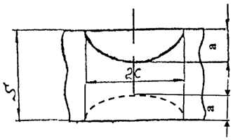
| 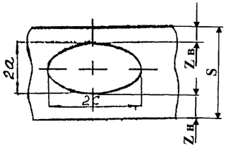
|
a) | b) |
Fig. 9.1. Discontinuities oriented
in the longitudinal direction (along the longitudinal axis of the equipment
or pipeline, or across a welded joint):
a) surface discontinuity,
b) subsurface discontinuity
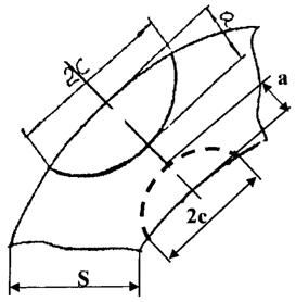
| 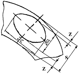
|
a) | b) |
Fig. 9.2. Discontinuities oriented in the circular
direction (across the longitudinal axis of the equipment
or pipeline, or along a welded joint):
a) surface discontinuity,
b) subsurface discontinuity
Appendix 10
to Federal rules and regulations in the area
of atomic energy use “Safety rules
for control of base metal, welded
joints and deposited surfaces
during operation of equipment,
pipelines and other components of nuclear power
plants" approved by order of the
of the Federal Environmental,
Industrial and Nuclear Supervision Service
dated 7 December 2015 No. 502
STANDARDS
PERMISSIBLE DISCONTINUITIES AND DEVIATIONS BASED ON THE RESULTS OF
VISUAL (TV) AND ULTRASONIC CONTROL
IN TECHNOLOGICAL CHANNELS AND CHANNELS OF CONTROL AND
PROTECTION SYSTEM OF RBMK REACTOR FACILITY
1. The standards establish the sizes of allowable deviations and discontinuities in the technological channels and the control and protection system channels of the RBMK reactor facility identified by methods of visual (television) control and ultrasonic control during in-core control.
2. The standards shall not be applicable to post-reactor control.
3. The technological channels and control and protection system channels shall be allowed into operation with deviations and discontinuities with dimensions not exceeding the values specified in Table No. 10.1 of this Appendix provided that other parameters (outer diameter, wall thickness, increase in length due to creep, bend deflection, the telescopic joints size, the graphite core condition) are within the limits specified by the standardized (regulations) and working programs, taking into account the actual condition of each NPP unit.
4. controlled reactor elements, which provide limited access for non-destructive control due to their design or the radiation environment shall be controlled using remote control devices.
5. The systems of operational non-destructive control used for in-core control should ensure the fulfillment of all requirements of these Rules.
Table No. 10.1
Controlled area | Control method | Controlled parameter | Assessment criteria | Note |
Process channel |
The inner surface of the middle section of the channel - Sb. 31 | Visual or television | Presence or absence of an oxide film and depositions | Presence of: iron-oxide depositions; surface discontinuities such as marks, cracks, dents and abrupt changes of the surface relief; peeling of iron-oxide depositions and/or zirconium oxide film. Not regulated quantatively | According to the oxide film type. In case of a black and white image according to the degree of blackness (black, gray, white), in case of a colored image – according to the color |
Subsurface inhomogeneities on the internal pipe wall (cracks, marks and scores to the base metal) | The static control mode shall identify and register all inhomogeneities (deviations) of all types and directions with the size of over 1.0 x 1.0 mm. The identified inhomogeneities may be designated as defects based on the analysis results by the operating organization together with the reactor facility project developer | |
The condition of steel-zirconium welds of adapters (presence of depositions and their lamination) | Presence of: opening of internal joints of steel-zirconium adapters or spalling of depositions on their surface; surface discontinuities such as marks, cracks, dents and abrupt changes of the surface relief; peeling of iron-oxide depositions and/or zirconium oxide film. Not regulated quantatively | According to the oxide film type. In case of a black and white image according to the degree of blackness (black, gray, white), in case of a colored image – according to the color |
Process channel |
Pipe and EAJ of the middle section of the channel - Sb. 31 | Ultrasonic | Presence and length of discontinuities (cracks, wear cavities, marks) | The quality of the base metal and the EBC metal shall be considered unsatisfactory if: amplitude of echo-signal received from the discontinuity is equal to or exceeds the amplitude of echo-signal received from a reference reflector of the 1.0 mm-deep mark type; amplitude of echo-signal received from the discontinuity is equal to or exceeds the amplitude of echo-signal received from a reference reflector of the 0.5 mm-deep mark type (registered level) and the conditional discontinuity length at the registered level is equal to 8.0 mm or more. When multiple (more than one) discontinuities appear with parameters of discontinuities not exceeding the ones indicated above, the matter of further operation of the technological channel shall be decided by a special substantiation prepared by the operating organization together with the reactor facility project developer | If discontinuities with the conditional dimensions exceeding the permissible ones are identified, it is necessary to either replace the technological channel or develop specialized equipment. Discontinuities shall be considered singular if the distance between them is not less than the conditional length of 8.0 mm |
Steel-zirconium adapters (the lower and upper internal joints) | Ultrasonic | Presence of opening of joints and discontinuities (cracks) | Opening of joints shall be registered. The quality of the sleeve metal shall be considered unsatisfactory if: amplitude of echo-signal received from the discontinuity is equal to or exceeds the amplitude of echo-signal of the rejection sensitivity level which is accepted as the level that is 4 dB lower than the reference level of an artificial reflector of the cylindrical hole type with a diameter of 2.0 mm | |
Channel of the control and protection system. |
The inner surface of the middle section of the channel - Sb. 35 | Visual or television | Presence or absence of an oxide film and depositions | Presence of: iron-oxide depositions; surface discontinuities such as marks, cracks, dents and abrupt changes of the surface relief; peeling of iron-oxide depositions and/or zirconium oxide film. Not regulated quantatively | According to the oxide film type. In case of a black and white image according to the degree of blackness (black, gray, white), in case of a colored image – according to the color |
Subsurface inhomogeneities on the internal pipe wall (cracks, marks and scores to the base metal) | The static control mode shall identify and register all inhomogeneities (deviations) of all types and directions with the size of over 1.0 x 1.0 mm. The identified inhomogeneities may be designated as defects based on the analysis results by the operating organization together with the reactor facility project developer | |
The condition of steel-zirconium welds of adapters (presence of depositions and their lamination) | Presence of: opening of internal joints of steel-zirconium adapters or spalling of depositions on their surface; surface discontinuities such as marks, cracks, dents and abrupt changes of the surface relief; peeling of iron-oxide depositions and/or zirconium oxide film. Not regulated quantatively | According to the oxide film type. In case of a black and white image according to the degree of blackness (black, gray, white), in case of a colored image – according to the color |
Channel of the control and protection system. |
Pipe and EAJ of the middle section of the channel - Sb. 35 | Ultrasonic | Presence and length of discontinuities (cracks, wear cavities, marks) | The quality of the base metal and the EBC metal shall be considered unsatisfactory if: amplitude of echo-signal received from the discontinuity is equal to or exceeds the amplitude of echo-signal received from a reference reflector of the 1.0 mm-deep mark type; amplitude of echo-signal received from the discontinuity is equal to or exceeds the amplitude of echo-signal received from a reference reflector of the 0.5 mm-deep mark type (registered level) and the conditional discontinuity length at the registered level is equal to 8.0 mm or more. When multiple (more than one) discontinuities appear with parameters of discontinuities not exceeding the ones indicated above, the matter of further operation of the control and protection system channel shall be decided by a special substantiation prepared by the operating organization together with the reactor facility project developer | If discontinuities with the conditional dimensions exceeding the permissible ones are identified, it is necessary to either replace the technological channel or develop specialized equipment. Discontinuities shall be considered singular if the distance between them is not less than the conditional length of 8.0 mm |
Steel-zirconium adapters (the lower and upper internal joints) | Ultrasonic | Presence of opening of joints and discontinuities (cracks) | The quality of the sleeve metal shall be considered unsatisfactory if: amplitude of echo-signal received from the discontinuity is equal to or exceeds the amplitude of echo-signal of the rejection sensitivity level which is accepted as the level equal to the reference sensitivity level corresponding to the echo-signal of an artificial reflector of the cylindrical hole type with a diameter of 1.0 mm | |
Appendix 11
to Federal rules and regulations in the area
of atomic energy use “Safety rules
for control of base metal, welded
joints and deposited surfaces
during operation of equipment,
pipelines and other components of nuclear power
plants" approved by order of the
of the Federal Environmental,
Industrial and Nuclear Supervision Service
dated 7 December 2015 No. 502
STANDARDS
OF PERMISSIBLE EXTENDED DISCONTINUITIES BASED ON THE RESULTS OF
ULTRASONIC CONTROL IN WELDED JOINTS NO. 23
OF DN1100 NOZZLES OF STEAM GENERATORS OF VVER-440 REACTOR FACILITY
1. The norms establish the dimensions of allowable extended discontinuities oriented along heterogeneous welded joints (pearlitic steel with austenitic steel) No. 23x and No. 23g of Dn1100 branch pipes of steam generators of VVER-440 units No. 3 and No. 4 of Novovoronezh NPP, No. 23 and No. 24 of Dn1100 branch pipes of steam generators of VVER-440 units No. 1, 2, 3, 4 of the Kola NPP, depending on the control frequency.
2. Sizes of acceptable extended discontinuities are specified in Table No. 11.1 of this Appendix.
Table 11.1
Total length of discontinuities, mm | The maximum height of discontinuities when the time until the next control or repair is, mm |
not more than 12 months | not more than 24 months | not more than 36 months | not more than 48 months |
Up to 462, inclusive | 19.0 | 17.0 | 15.0 | 13.0 |
From 463 to a circular | 16.0 | 14.0 | 12.0 | 10.0 |
3. Welded joints with identified discontinuities exceeding the dimensions specified in Table No. 11.1 of this Appendix are subject to repair.
4. If a discontinuity not exceeding the dimensions specified in Table No. 11.1 of this Appendix is detected on a welded joint for the first time, such welded joint shall undergo operational control during the next scheduled shutdown of the NPP unit and an estimate of the discontinuity propagation rate.
5. If a change in previously fixed discontinuity dimensions of leads to exceeding the permissible value before the expiration of the period specified in Table No. 11.1 of this Appendix, the frequency of the welded joint control shall be reduced or the welded joint shall be repaired.
Appendix 12
to Federal rules and regulations in the area
of atomic energy use “Safety rules
for control of base metal, welded
joints and deposited surfaces
during operation of equipment,
pipelines and other components of nuclear power
plants" approved by order of the
of the Federal Environmental,
Industrial and Nuclear Supervision Service
dated 7 December 2015 No. 502
STANDARDS
OF PERMISSIBLE EXTENDED DISCONTINUITIES BASED ON THE RESULTS OF
ULTRASONIC CONTROL IN THE CROSS-POINT OF HEAT MEDIUM
HEADER TO DТ1200 NOZZLES OF STEAM GENERATORS OF
VVER-1000 REACTOR FACILITY
1. The standards establish the dimensions of allowable extended discontinuities with longitudinal and transverse orientation relative to the welded joint of the cross-point of welding of a heat medium header to Dn1200 nozzles of the steam generators of VVER-1000 reactor facility. The sizes of permissible extended longitudinal discontinuities are specified in Table No. 12.1 of this Appendix and extended transverse discontinuities – in Table No. 12.2 of this Appendix.
Table 12.1
Total length of a discontinuity along a welded joint, mm | Maximum discontinuity height, mm, not more than |
Up to 400, inclusive | 13 |
Over 400 and up to 1000, inclusive | 8 |
Over 1000 | 5 |
Note. The limits specified in this table also apply to the longitudinal projection of diagonal discontinuities. |
Table 12.2
Total length of a discontinuity across a welded joint, mm | Maximum discontinuity height, mm, not more than |
Up to 40, inclusive | 13 |
Over 40 and up to 60, inclusive | 8 |
Over 60 | 5 |
Note. The limits specified in this table also apply to the transverse projection of diagonal discontinuities. |
3. Welded joints with identified discontinuities exceeding the dimensions specified in Tables No. 12.1 and 12.2 of this Appendix are subject to repair.
3. Each welded joint with an extended discontinuity, approved for operation, shall be subjected to operational control during each further scheduled NPP unit shutdown.
Appendix 13
(for reference)
to Federal rules and regulations in the area
of atomic energy use “Safety rules
for control of base metal, welded
joints and deposited surfaces
during operation of equipment,
pipelines and other components of nuclear power
plants" approved by order of the
of the Federal Environmental,
Industrial and Nuclear Supervision Service
dated 7 December 2015 No. 502
STANDARDS
OF PERMISSIBLE DISCONTINUITIES BASED ON THE RESULTS OF EDDY CURRENT
CONTROL OF VVER TYPE REACTOR FACILITIES
1. The standards shall be applied to assess the condition of metal during eddy current control of the following parts of VVER reactor facility:
a) steam generator heat exchanging pipes;
b) crossover pipes of headers of the primary circuit coolant.
2. Standards for the assessment of condition of metal of the heat exchanging pipes based on the results of eddy current control have been established for discontinuities directed along the heat exchanging pipes axis.
3. The standards consider a discontinuity or damage to the pipe to be unacceptable if it requires its plugging.
4. If there are no measuring control means which could obtain data on the length of the heat exchanging pipes metal discontinuities with a depth of 60 to 87% (inclusive), it is allowed to apply amplitude control criteria in accordance with Tables No. 13.1, 13.2 and 13.2 of this Appendix depending on the type of devices used.
Table 13.1
Amplitude criteria for control using the flaw detector
HARMONIC-210 in case of 1.4 V conditioning at the frequency of 130 kHz
Allowable discontinuity depth, % of the nominal wall thickness of heat exchanging pipes | Signal amplitude at the open section of heat exchanging pipes, B | Signal amplitude under the spacer grid, B |
From 60 and up to 68, inclusive | less than 0.63 | less than 0.55 |
Over 68 and up to 77, inclusive | less than 0.58 | less than 0.50 |
Over 77 and up to 87, inclusive | less than 0.38 | less than 0.33 |
Table 13.2
Amplitude criteria for control using the flaw detectors
MIZ-70, MIZ-30, MIZ-85, OMNI-200 in case of 10.0 V conditioning
at the frequency of 100 kHz
Allowable discontinuity depth, % of the nominal wall thickness of heat exchanging pipes | Signal amplitude at the open section of heat exchanging pipes, B | Signal amplitude under the spacer grid, B |
From 60 and up to 68, inclusive | less than 3.63 | less than 3.16 |
Over 68 and up to 77, inclusive | less than 3.33 | less than 2.90 |
Over 77 and up to 87, inclusive | less than 2.21 | less than 1.92 |
Table 13.3
Amplitude criteria for control using the TEDDY flaw detector
in case of 5.0 V conditioning at the frequency of 140 kHz
Allowable discontinuity depth, % of the nominal wall thickness of heat exchanging pipes | Signal amplitude at the open section of heat exchanging pipes, B | Signal amplitude under the spacer grid, B |
From 60 and up to 68, inclusive | less than 1.64 | less than 1.43 |
Over 68 and up to 77, inclusive | less than 1.50 | less than 1.31 |
Over 77 and up to 87, inclusive | less than 1.00 | less than 0.87 |
Notes. 1. Amplitude criterion assessment shall be carried out by means of conditioning of the signal of the reference sample supplied with the flaw detector: with three through holes with a diameter of 1.30 mm, arranged in cross section at an angle of 120° – for eddy current systems with flaw detectors MIZ-30, MIZ-70, MIZ-85, OMNI-200; with four through holes with a diameter of 1.20 mm, arranged in cross section at an angle of 90° – for eddy current systems with the HARMONIC flaw detector; with four flat-bottomed holes with a diameter of 4.75 mm, arranged in cross-section at an angle of 90° – for eddy-current systems with the TEDDY flaw detector. 2. The use of the amplitude criterion for systems with flaw detectors not listed in Tables No. 13.1, 13.2, 13.3 of this Appendix shall be carried out in the manner prescribed in Chapters V and XIII of these Rules. |
5. Assessment of the condition of crossover pipes metal of headers of the primary circuit coolant shall be carried out by comparing the signal received from the discontinuity with the signal from the reference sample groove and determination of the identified discontinuity length. The dimensions of the reference sample groove are specified in Table No. 13.4 of this Appendix.
6. Eddy current control of crossover pipes metal shall be carried out throughout the thickness of the base metal of the header wall. The discontinuities which signal exceeds the signal from the groove of the reference sample with a depth of 3.0 mm, and which length exceeds 20.0 mm, shall not be allowed.
Table 13.4
Minimum recordable level | Maximum allowable level |
Depth, mm | Length, mm | Width, mm | Depth, mm | Length, mm | Width, mm |
1.0 | 10.0 | 0.3 | 3.0 | 20.0 | 0.3 |
Notes. 1. The tolerance for the dimensions of a rectangular groove during manufacture shall not exceed +/- 10%. 2. Reference samples shall be made of the same material as the material of the control area. |
Appendix 14
to Federal rules and regulations in the area
of atomic energy use “Safety rules
for control of base metal, welded
joints and deposited surfaces
during operation of equipment,
pipelines and other components of nuclear power
plants" approved by order of the
of the Federal Environmental,
Industrial and Nuclear Supervision Service
dated 7 December 2015 No. 502
GENERAL DECISION-
MAKING FLOW CHART BASED ON THE RESULTS OF OPERATIONAL
NON-DESTRUCTIVE CONTROL OF THE METAL OF EQUIPMENT, PIPELINES
AND OTHER COMPONENTS OF NUCLEAR POWER PLANTS
3. The general flow chart of decision-making based on the operational non-destructive control results for the metal of equipment, pipelines and other NPP components is presented on Figures 14.1 and 14.2 of this Appendix.
2. The term used in this Appendix.
Values of control indicators that exceed the registration level are the values from which non-destructive control indicators shall be documented, analyzed and compared with the values of indicators of previous controls; indicators are expressed in conditional parameters (for example, equivalent area or conditional length) or physical units (for example, geometric dimensions).
┌───────────────────────┐
│ Operation │
┌────────────────────────>│ of a NPP unit │
│ └───────────┬───────────┘
│ \/
│ ┌───────────────────────┐
│ │ 0. Operational │
│ │ control │
│ └───────────┬───────────┘
│ \/
│ ┌───────────────────────┐
│ │1. Control indicators │
│ │ (registration level) │
│ └───────────┬───────────┘
│ \/
│ ─────────────────── ┌───────────────────────────┐
┌───────────┴─────────┐ / 2. Indicators \ yes │ Comparison to the results │
│ │ no / of control exceed \───>│ of previous control │
│ 13. Permit for │ ┌─────\ registration level / └───────────┬───────────────┘
│ operation │ │ \ / \/
│ │ │ ─────────────────── ───────────────
└─────────────────────┘ │ no /3. Discontinuity \ yes
/\ │ ┌────\ (deviation) /────┐
│ │ \/ ─────────────── \/
┌──────────┴─────────┐ │ ───────────── ────────────────
│ │<────────┘ / \ / 5. Indicators \ no
│ 12. Technical │ no / 4. Indicators \ yes/ of discontinuity \──┐
│ examination │<─────────────────────────────────\ increased /───>\(deviations) or its / │
│ │ \ / \ increase are / │
│ │ \ / \ allowable / │
└────────────────────┘ ─────────── ───────┬────── │
/\ /\ yes │ │
│ └────────────────────────────────────────────────────────────────────────────┘ │
│ ┌──────────────────┐ │
│ │6. Additional │ │
│ │ control for │<─┘
┌─────┴───────────────────────────────────────────────┐ │ detection of │
│9. Exclusion of reasons, additional (compensating) │<─────────────┐ │ defect parameters│
└─────────────────────────────────────────────────────┘ │ └─────────┬────────┘
/\ │yes \/
│ ─────┴───── ┌───────────────────────┐
┌────────────────┴────────────────┐ ┌───────────────────────┐ / 8. \ │7. The analysis of │
│11. Pre-operation control │ │10. Defect correction │ no / Discontinuity \ │causes of defect │
│ of a repaired assembly │<─┤(repair) or replacement│<───\ (deviation) is/<─┤appearance, assessment │
└─────────────────────────────────┘ └───────────────────────┘ \ acceptable / │of results of │
─────────── │non-destructive control│
└───────────────────────┘
Fig. 14.1. The decision-making flow chart and assessment of acceptability of
discontinuity during operational control
of the metal of equipment, pipelines and other NPP components
from stage 6
│
\/
┌─────────────────────────────────────────┐
│ │
┌────────────┴─────────────┐ ┌───────────┴──────────────┐
│ Assessment of indicators │ │ Assessment of indicators │
│ of non-destructive │ │ of non-destructive │
│control in physical units │ │control in physical units │
└────────────┬─────────────┘ └────────────┬─────────────┘
│ │
\/ \/
─────────────────────── ──────────────── ┌───────────────────────────┐
/ There are standards \ / There are tables \ │Justification of acceptable│
/ for assessment of \yes yes / of acceptable sizes\ no │ discontinuity sizes │
\ quality for manufacturing,/─┐ ┌────\ of discontinuities /───────────>│ (deviations) for │
\which apply to operation / │ │ \ (deviations) / │ the specified period │
───────────┬─────────── │ │ ──────────────── └──────────┬────────────────┘
│ │ │ │
│no │ │ │
\/ │ │ \/
──────────────── │ │ ─────────────────────
/ Indicators \ │ │ / Indicators of control \
/ of control exceed \ │ └────────────────┐ no / exceed acceptable size \yes
┌─\ the rejection / │ │ ┌───\ (based on /──┐
│ \ criteria / │ │ │ \ justification) / │
│no ───────┬──────── \/ \/ │ ───────────────────── │
│ yes│ ─────────────────── ─────────────────── │ │
│ │ /Indicators of control\ /Indicators of control\ │ │
│ │ / exceed the rejection \ / exceed the rejection \ │ │
│ │ ┌─\ criteria based on /─┐ ┌─\ based on tables /─┐ │ │
│ │ │ \ operation standards / │ │ \ / │ │ │
│ │ │no ─────────────────── yes│ │no ─────────────────── yes│ │ │
│ └─(───────────────────────────о─(───────────────────────────о──(───────────────────────────────\/
│ │ │ │ │
\/─────────────о─────────────────────────────о───────────────────────────)──┘
│ │
\/ \/
┌──────────────────────────────┐ ┌──────────────────────────────────┐
│ Discontinuity (deviation) is │ │ Discontinuity (deviation) is not │
│ acceptable in this structure │ │ acceptable in this structure │
└────────────┬─────────────────┘ └─────────────┬────────────────────┘
└─────────────────────────────┬─────────────────────────┘
│
\/ to stage 8
Fig. 14.2. The decision-making flow chart and assessment of acceptability of
discontinuity during operational control
of the metal of equipment, pipelines and other NPP components
(explanation of stage 7 is presented in Fig. 14.1 of this Appendix)
3. The general flow chart of decision-making based on the operational control results for the metal of equipment, pipelines and other NPP components shall include the following steps:
Stage 0 – conducting operational non-destructive control in accordance with the requirements of the standardized control program.
Stage 1 – registration of control indicators exceeding the registration level.
Stage 2 – evaluation of non-destructive control indicators exceeding the registration level.
Stage 3 – identification of new discontinuities in comparison with the values of the previous non-destructive control indicators (if there have been no new discontinuities, then an analysis of changes in the values of previously registered discontinuities shall be performed).
Stage 4 – identification of changes in the values of discontinuities registered during the previous non-destructive control (if a change in indicators is detected, the value of the changes shall be evaluated and a conclusion shall be made regarding the causes and time of these changes).
Stage 5 – acceptability assessment for the values of discontinuity and/or its propagation (comparison of discontinuity values with rejection criteria for identifying defects, and acceptability assessment for the emergence of new discontinuities or increase in values of previously recorded discontinuities).
Step 6 – if discontinuities are detected for the first time or there is an increase in the values of the discontinuities detected during previous controls, it is necessary to perform an additional non-destructive measuring control, make a conclusion about the type, position and value of the discontinuity, and establish the reason for its appearance (propagation).
Stage 7 – analysis of the reasons for the emergence of new discontinuities or an increase in the propagation rate of previously registered discontinuities (stage 7 is shown in detail in Fig. 14.1 of this Appendix):
a) if the condition of equipment, pipelines and other NPP components has changed, that is, new values of non-destructive control indicators have been identified, or an increase in values of previously registered discontinuities has been detected, it is necessary to make a conclusion regarding the causes and speed of these changes taking into account the results of previous non-destructive control;
b) if it is confirmed that a new condition has arisen, that is, a new unacceptable discontinuity has emerged during the operation and has been identified, or the values of the previously registered discontinuities have increased, the further operation of equipment or pipelines is allowed only after the elimination of defects. If the causes of discontinuities are not established, it is necessary to develop substantiation of the safe operation of the repaired equipment or pipelines until the next shutdown of the NPP unit. The decision on the possibility of further operation and the schedule of further operational control of equipment and pipelines is made by the operating organization based on the results of the substantiation prepared. This decision shall be agreed by the reactor facility project and/or the NPP project developers, the manufacturer (for equipment referred to the first class safety), the leading materials science organization and submitted together with the substantiation results and the conclusion by the technical support organization of the competent state authority regulating safe use of atomic energy for consideration to the competent state authority regulating safe use of atomic energy;
c) in order to establish the reasons for the emergence of a new discontinuity or propagation of previously identified discontinuity, and make a decision, it is necessary to establish a special commission. The commission should include representatives of the operating organization, representatives of the lead material science organization, the design (engineering) organization and representatives of the manufacturer;
d) the following shall be carried out in the course of commission activities:
additional double check measuring control, in order to specify the geometric dimensions of a discontinuity, as well as control of similar places and assemblies with similar loads and working conditions;
analysis of the results of the strength check calculation according to the standard requirements, or if it is not available - carrying out of relevant strength check calculation;
calculation of acceptable discontinuities in the metal of equipment and pipelines shall be performed by means of fracture mechanics methods. Assessment of acceptability of the identified discontinuity shall be carried out according to the standards for permissible discontinuities during operation established by these Rules.
The results of the commission’s work, control reporting documents and the commission’s conclusions shall be provided to the operating organization.
Stage 8 – depending on the nature and size of the identified discontinuity, the commission prepares relevant proposals. The identified causes and results of the analysis of the discontinuity causes and development mechanism shall be considered when establishing the limit of permissible discontinuity and deciding whether the operation of equipment, piping or another NPP component with an identified discontinuity is acceptable or not.
Stage 9 – if the nature and size of the identified discontinuity comply with the standards for allowable discontinuities at the operation stage, the commission provides proposals on the possibility of accepting equipment, pipelines and other NPP components with identified discontinuity for operation provided the elimination of its reasons and the implementation of additional (compensating) measures.
Stage 10 – if the nature and size of the identified discontinuity does not comply with the standards for allowable discontinuities at the operation stage, the commission comes up with proposals on the need to correct the identified discontinuity (unit repair) and/or replace the component, eliminate the reasons for its occurrence and implement additional (compensating) measures.
Based on the commission’s conclusion and proposals, the operating organization makes the appropriate decision about the possibility of accepting the equipment, pipeline or other NPP component for operation, replacing the equipment, or making repairs.
Stage 11 – in case equipment, pipelines and other NPP components are replaced or repaired, the replaced equipment, pipeline section or other NPP component or repaired section shall undergo pre-operational control prior to the commencement of their operation.
Stage 12 – technical examination of the repaired assembly or replaced equipment, pipeline or other NPP component.
Stage 13 – preparation of a permit for the operation of the equipment, pipeline or other NPP component based on the results of their control and technical examination.
4. If a decision is made to put equipment, pipelines and other NPP components with an identified discontinuity into operation, the cause of such discontinuity shall be eliminated and, if necessary, additional measures (step 9) shall be taken, for example:
a) the intervals between controls may be reduced;
b) the structure may be reinforced;
c) the operation conditions of equipment, pipelines and other NPP components with an identified discontinuity may be changed;
5. If a decision is made to repair or replace equipment, pipeline or other NPP component (steps 9 and 10), it is necessary to eliminate the cause of the discontinuity and monitor the effectiveness of the work performed during further operation by:
a) installing measuring devices;
b) decreasing the intervals between controls;
c) increasing the scope of control;
d) if it is necessary, changing the operating conditions of the repaired assembly or replaced equipment, pipeline or other NPP component.
6. If the analysis of the results of ultrasound or eddy current control uses the method of evaluating the results by images, the registration levels shall be visible in the image, and the procedure for evaluating the control results by images shall be strictly formalized.