Approved by the
Decree of the Federal
Environmental, Industrial
and Nuclear Supervision
Service dated November 14, 2018. No. 554
FEDERAL RULES AND REGULATIONS
IN THE FIELD OF USE OF ATOMIC ENERGY "WELDING AND
SURFACING OF EQUIPMENT AND PIPELINES OF NUCLEAR
POWER INSTALLATIONS"
(NP-104-18)
I. Purpose and scope of application
1. These Federal Rules and regulations in the Field of Nuclear Energy Use "Welding and Surfacing of Equipment and Pipelines of Nuclear Power Installations" (NP-104-18) " (hereinafter referred to as the Rules) were developed in compliance with Federal Law dated November 21, 1995. No.170-FZ "On atomic energy use", Provisions for development and approval of federal rules and regulations in the field of atomic energy use approved by Decree of the Government of the Russian Federation No. 1511 dated 1 December 1997 N 1511 (Code of legislation of the Russian Federation, 1997, N 49, art. 5600; 2012, N51, art. 7203).
2. These Rules establish requirements for the manufacture, installation and repair of equipment and pipelines of nuclear power installations:
a) to perform welding and surfacing, including welding materials, welding equipment, preparation and assembly for welding, types of welded joints, heat treatment of welded joints and surfaced parts;
b) to control of the quality of welding and surfacing materials;
c) to elimination of defects and control over the same.
Requirements for welding and surfacing should be taken into account in the development of engineering (design) documentation.
3. These Rules apply to the performance of welding and surfacing of parts and assembly units:
a) the equipment and pipelines subject to federal rules and regulations in the field of atomic energy use "Rules of the design and safe operation of the equipment and pipelines of nuclear power installations" (NP-089-15) approved by the order of the Federal Service for Environmental, Industrial and Nuclear Supervision dated December 16, 2015 No. 521 (registered by the Ministry of Justice of Russia on February 9, 2015, registration No. 41010) (hereinafter referred to as NP-089-15);
b) the equipment and pipelines working under excessive or vacuum pressure and referred to elements of the third class of safety not subject to NP-089-15;
c) supports and hangers of equipment and pipelines specified in subparagraphs "a" and "b" of this paragraph;
d) internals of water-water reactors and reactors on fast neutrons;
e) metalworks of fuel holding pools, refueling ponds, spent fuel pools of nuclear power installations.
4. These Rules establish requirements to performance of welding of parts and assembly units of equipment and pipelines made of the following materials:
a) of steel grades St3sp5, 10, 15, 20, 15L, 20L, 25L, 20K, 22K, 15GS, 16GS, 20GSL, 09G2S, 09G2SА-A, 10KhSND, 10KhN1М, 16GNMA, 12MKh, 12KhM, 15KhM, 20KhM, 20KhМА, 10Kh2M, 12Kh1MF, 15Kh1M1F, 10GN2MFA, 10GN2MFA-A, 12Kh2MFA, 12Kh2MFA-AD, 15Kh2MFA, 15Kh2MFA mod. A, 15Kh2MFA-A, 15Kh2MFA-A mod. A, 15X2MFA-A mod. B, 18Kh2MFA, 18Kh2MF A-A, 15Kh2NMFA, 15Kh2NMFA-A, 15Kh2NMFA class 1, 15Kh2NM1FA, 15Kh2NM1FA-A, 15Kh3NMFA, 15Kh3NMFA-A (these will be hereinafter referred to as the steels of pearlitic class, steel grades St3sp5, 10, 15, 20, 15L, 20K, 25K, 20K, 22K hereinafter referred to as the carbon steel grades 15GS, 16GS, 20GSL, 09G2S, 09G2SA-A - silico-manganese, and other steel grades - alloyed ones);
b) of steel grades 08Kh13, 10Kh9MFB, 05Kh12N2М, 06Kh12N3D, 06Kh12N3DL, 08Kh14MF, 07Kh16N4B, 07Kh12NFMB (these will be hereinafter referred to as high-chromium ones);
c) of steel grades 08Kh18N9, 09Kh18N9, 10Kh18N9, 12Kh18N9, 08Kh18N10, 03Kh16N9М2, 08Kh16N11М3, 12Kh18N12M3TL, 12Kh18N9T, 12Kh18N9TL, 06Kh18N10T, 08Kh18N10T, 12Kh18N10T, 08Kh18N12T, 12Kh18N12Т, 10Kh17N13M2T, 10Kh17N13M3T, 03Kh22N5АМ3, 03Kh25N7АМ4 (these will be hereinafter referred to as austenitic steels);
d) of iron nickel alloys 03Kh21N32М3B, KhN35VT, KhN78T;
e) of pearlitic class steels with parts made of high-chromium steels, austenitic steels and iron-nickel alloys;
f) of high-chromium steels with austenitic steel parts;
g) of titanium and its alloys of grades VT1-00, VT1-0, PT-1M, PT-3V, PT-7M, 3M, 5V, 5 VL, TL3, TL5, 19;
h) of aluminum alloys of grades ADOO, ADO, AD1, AD, AV, SAV1, AMg2, AMg3.
Further, the welding of parts made of materials listed in subparagraphs "e" and "f" of this paragraph is referred to as the welding of parts made of steels of different structural classes.
These Rules also establish requirements for the performance of welding of parts of two-layer steels with the base layer of carbon or alloy steel, and a plating layer of steel 08Kh18N10T, or 08Kh19N10G2B, or with anti-corrosion cladding made with, among others, Sv-08Kh19N10G2B Sv-04Kh20N10G2B, Sv-03Kh22N11G2B, Sv-03Kh24N13G2B.
5. These Rules establish requirements to performance of surfacing of details from the materials listed in subparagraphs "a" -"d", "g" of paragraph 4 of these Rules.
6. Welding and surfacing must be carried out in accordance with the process documentation developed taking into account the requirements of these Rules and engineering documentation.
7. Process documentation for welding and surfacing of parts and assembly units of equipment and pipelines manufactured (mounted) before the entry into force of these Rules or being in the manufacture (installation) at the time of their entry into force, shall not be subject to revision.
8. Process documentation for the repair of welded joints and overlaid surfaces of equipment and pipelines repaired prior to the entry into force of these Rules or being under repair at the time of entry into force of these Rules shall not be subject to revision.
9. Welding and surfacing of equipment and pipelines should be performed by personnel who have passed theoretical and practical training and is allowed to work independently in the manner prescribed by the organization performing these works.
10. The terms and definitions used are given in Appendix No. 1 to these Rules.
II. Welding and surfacing materials
11. Information on the materials applied for performance of welding (surfacing) of parts and assembly units of the equipment and pipelines are given in Appendix N 2 to these Rules.
At welding (surfacing), materials must be used admitted for use subsequent to requirements of standardization documents included into the Consolidated List of standardization documents in the field of atomic energy use, which shall be used without fail (hereinafter referred to as the Consolidated List) as stipulated in the Regulations on standardization for the products (works, services) subject to requirements related to safety assurance in the area of atomic energy use as well as processes and other standardization objects associated with such products, approved by Decree of the Government of the Russian Federation dated July 12, 2016 No. 669 (Collected legislation of the Russian Federation, 2016, No. 29, Art. 4839).
12. For the use of welding (surfacing) materials not included in the Consolidated List, a conformity assessment in the form of certification tests of the material must be carried out. Requirements to the certifying tests substantiating the application of a new welding (surfacing) material are given in Appendix N 3 to these Rules.
The welding (surfacing) material should be used after the inclusion of the material standardization document in the Consolidated List.
III. Welding equipment
13. To perform welding and surfacing, equipment and measuring instruments must be used ensuring compliance with the requirements of these Rules.
14. The applied equipment shall provide observance in permissible limits of the parameters of the modes of welding (surfacing) established in the process documentation.
15. Equipment for argon arc welding with a non-consumable electrode and plasma surfacing with powder materials should be furnished with devices for smooth arc quenching.
16. Metrological support of measuring instruments used in welding and surfacing shall be carried out in accordance with the legislation on ensuring the uniformity of measurements.
IV. Control of the quality of welding and surfacing materials
General requirements
17. All the batches of welding and surfacing materials intended for welding and surfacing of equipment and pipelines are subject to control.
18. The control of the quality of welding and surfacing materials includes:
a) check of cover documentation;
b) check of packaging and the condition of welding and surfacing materials;
c) control of the metal of seam and the metal of surfacing.
19. Control of quality of welding and surfacing materials shall be exercised by the organization using these materials at welding (surfacing) of the equipment and pipelines.
20. Control of quality of each batch of welding and surfacing materials should be carried out prior to their use.
21. With the organization-manufacturer of the equipment and (or) assembly units of pipelines using welding (surfacing) materials of their own production, it is allowed to have combination of quality control of welding and surfacing materials with acceptance control of specific batches of welding and surfacing materials.
Check of cover documents
22. Each batch of welding and surfacing materials should be checked:
(a) for availability of a certificate (or label for gas cylinders) with the verification of the completeness of the data contained therein and their compliance with the requirements of the standardisation documents for welding and surfacing materials included in the Consolidated List;
b) for each packaging place having marking indicating the brand, gauge and batch number of the material.
23. The results of the inspection of materials are documented by log entries. In addition to the welding material inspection log, a log of baking of coated electrodes and welding fluxes must be kept to ensure that they can be used after baking.
24. The composition and content of the reporting documentation for the control of materials used for welding and surfacing works during repairs of equipment and pipelines are determined by the operating organization.
Check of packaging and the condition of welding
(surfacing) materials;
22. Each batch of welding (surfacing) materials should be checked:
a) for absence of damage of package and (or) materials as such;
b) on compliance with the certificate data and requirements of the documents on standardization included in the Consolidated List.
26. At the check of welding (surfacing) materials, the following shall be controlled:
a) each batch of the covered electrodes - on compliance of the nominal sizes of electrodes with the data of the certificate and the condition of their coverage with requirements of the documents on standardization included in the Consolidated List;
b) each batch of welding (surfacing) wire and tape - for compliance of the nominal sizes and type of the surface with the data of the certificate and the condition of the surface with requirements of the documents on standardization included in the Consolidated List, as well as for existence of marking from two sides of the coil of welding wire and tape;
c) each batch of flux - for compliance of color, uniformity and granulometric structure with requirements of the documents on standardization included in the Consolidated List.
27. The decision on further full or partial use of welding (surfacing) materials in case of damage of packaging and (or) materials shall be made by the organization applying the specified materials.
28. Each batch of coated electrodes and fluxes before use should be checked for compliance of moisture content in the coating of electrodes and flux moisture with requirements of documents on standardization of controlled welding materials included in the Consolidated List, or for compliance with the conditions and terms of storage after the next baking.
29. When using a batch of coated electrodes or flux in parts, the moisture content of the coating and the moisture content of the flux must be checked separately for each part of the batch to be used.
Repeated baking should be carried out in cases where the moisture content in the coating of the electrodes or the moisture content of the flux exceeds the norms established by the standardization documents included in the Consolidated List, as well as in case of violation of the conditions and terms of storage after baking.
30. The requirements to storage of welding (surfacing) materials are presented in Appendix 4 to these Rules.
Control of the metal of seam and the metal of surfacing
31. The following shall be subject to control:
a) each melt of welding wire and tape;
b) each batch of electrodes, fluxes and powder materials.
32. For performance of welding (surfacing) materials, reference weld seams (overlays) shall be made.
33. Reference weld seams are subject to total visual, measuring and radiographic or visual, measuring and ultrasonic inspection.
34. Reference overlays are subject to total visual and capillary or visual and magnetic powder (except for surfacing made of austenitic materials) control, and in cases provided for by the process documentation, ultrasonic and (or) radiographic control, as well.
35. Reference weld seams and reference overlays are subject to nondestructive testing (in the initial state after welding and (or) after heat treatment, if it is required), upon the positive results of which destructive testing is carried out.
If the total length of the defective areas detected during nondestructive testing does not exceed 5% of the length of the reference weld seam or the reference overlay, the destructive testing shall be carried out from samples not cut from the defective areas.
36. The results of non-destructive and destructive testing of reference weld seams and reference overlays must meet the requirements of federal rules and regulations in the field of atomic energy use regulating the control of metal equipment and pipelines of nuclear power installations in the manufacture and installation.
37. The assessment of results of nondestructive testing should be performed depending on categories of welded joints which must meet higher requirements for assurance of safety.
Categories of welded joints are established in engineering documentation according to requirements of federal rules and regulations in the field of atomic energy use regulating control of metal of the equipment and pipelines of nuclear power installations at production and installation.
If the category of welded joints is not established, the nondestructive testing shall be evaluated according to the standards established for welded joints of category III.
38. In case of unsatisfactory results of non-destructive testing of reference weld seams and overlays, depending on the nature of the identified defects, a decision is made to re-apply reference weld seams or overlays after additional operations to improve the quality of welding consumables or the impossibility of using controlled welding consumables for welding (surfacing) equipment and pipelines.
39. In case of unsatisfactory results of destructive testing tests should be repeated by a specific method of destructive testing on a doubled number of samples. The results of repeated tests shall be definitive.
40. Reference weld seams must be performed:
a) in the control of coated electrodes for manual arc welding - with electrodes of each batch;
b) in the control of welding materials for automatic submerged arc welding and electroslag welding - with welding wire of each melting in combination with the flux of each batch;
c) in the control of welding materials for welding in a protective gas atmosphere (mixture of inert gases) - with welding wire for each melting combined with the protective gas of the same brand and same type (with a mixture of protective gases in the same proportions).
The reference weld seams should be made of welding materials used for industrial welding joints.
41. Reference overlays must be performed:
a) at control of the coated electrodes for manual arc surfacing - with electrodes of each batch;
b) in the control of welding materials for automatic submerged arc welding and electroslag welding - with welding wire or tape of each melting in combination with the flux of each batch;
c) in the control of welding materials for welding in a protective gas atmosphere (mixture of inert gases) - with welding wire for each melting or powder of each batch combined with the protective gas of the same brand and same type (with a mixture of protective gases in the same proportions).
Reference overlays should be made of materials used in the performance of industrial surfacing.
42. Instead of reference welding seams, reference surfacing is performed, provided that the batch (the set of batches of filler materials) of welding materials is to be used for welding parts:
a) of carbon or austenitic steels with a nominal thickness of up to 40.0 mm inclusive;
b) of silica-manganese steels with nominal thickness up to 30.0 mm inclusive;
c) of alloy steels or high-chromium steels with a nominal thickness of up to 20.0 mm inclusive.
43. If a batch (a set of batches) of welding materials is to be used both for welding, and for surfacing, only a reference welding seam is made, and in cases stipulated by paragraph 42 of these Rules, only a reference overlay.
44. To perform welding of parts with nominal thickness up to 20.0 mm, welding materials are used for welding of the root layers of the seam.
45. It is allowed not to perform reference welding seams if the design documentation provides for the performance of destructive testing of industrial welding joints.
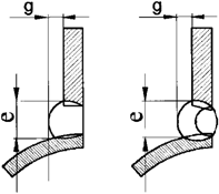
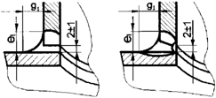
46. When performing reference welding seams, the combination of grades of the base metal of the welded plates (parts) and the controlled welding materials must comply with the requirements of these Rules.
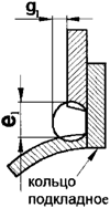
Plates made of steel of other grades of the same structural class are used on condition of preliminary surfacing of the edges subject to welding with welding materials of the controlled grade (combination of grades) not less than in three layers. For the specified surfacing of edges welding materials of other batches of welding materials of the same grade, including welding materials of other size, can be used.
Plates made of steel of other structural classes are used under the condition of preliminary surfacing on the edges of with at least five layers.
In the control of welding materials intended for welding of parts of steels of different structural classes, plates made of a material, on which no pre-surfacing of edges is required, are used.
47. When performing reference welding seams by automatic submerged arc welding or argon arc welding, three-layer edge welding shall be carried out by manual arc welding with coated electrodes approved for welding the same steels as the controlled welding materials.
48. The thickness of welded plates (parts) at performance of reference welding seams shall be established in process documentation with observance of the following conditions:
a) at use of a controlled batch (combination of batches) of welding materials for the production of welded joints with preliminary and accompanying heating, the thickness of the plates (parts) shall not be less than the thickness, beginning from which, according to these Rules, heating is required;
b) at use of a controlled batch (a combination of batches) of welding materials for the production of industrial butt-welded joints subject to thermal treatment, the thickness of plates (parts) should be not less than the thickness, starting from which, according to these Rules, heat treatment is required;
c) the thickness of the welded plates (details) shall be not less than 14.0 mm at arc welding and 30.0 mm - at electroslag welding.
49. The length of the welded plates (total length at welding of several pairs of plates), along the extent of a welded seam, shall provide selection of the necessary quantity of samples for carrying out all tests of metal of the seam provided by these Rules.
50. The width of each of the welded plates (parts) shall make not less than 300.0 mm at electroslag welding, not less than 150.0 mm at automatic submerged arc welding and not less than 80.0 mm at other methods of welding.
51. Dressing the edges of plates (parts) shall be allowed to carry out with any type of butt-welded joint used in welding the parts of appropriate thickness, or with a type of welded joints provided by documents on standardization for welding consumables included in the Consolidated List.
52. For performance of reference welding seams and overlays, welding equipment must be used ensuring the compliance of all the parameters of the welding conditions established by process documentation for the production of welded joints and surfacing.
Welding conditions must correspond to the modes used in the performance of one of the production welds with controlled welding materials.
Reference welding seams are performed in the lower position, unless other requirements are specified in the engineering documentation.
53. The necessity and temperature conditions of prior and accompanying heating at performance of reference welding seams shall conform to the requirements of these Rules established for production welded joints.
If a controlled batch (combination of batches) of welding materials is to be used for various production welds, for which the minimum prior heating and accompanying heating temperature specified in the process documentation differ by more than 50 °C (including the case where no heating is required), two reference seams shall be welded.
54. At welding of the first reference welding seam, the minimum heating temperature must correspond to the lowest temperature (including without heating), and at welding of the second one - to the highest of the minimum temperatures set for heating for welding of steel parts of the corresponding grades and thicknesses. If individual production parts are to be welded without heating, welding of the first reference seam shall also be carried out without heating.
55. The need, type and modes of heat treatment of reference welding seams must meet the requirements for the performance of production welded joints.
56. In case of repeated heat treatment of industrial welded joints, the same heat treatment should be applied to reference welding seams, as well.
In case of multiple tempering operations, the reference welding seam may be subjected to a single tempering operation with a duration of exposure at each temperature not less than 80% and not more than 100% of the total duration of the corresponding exposures at the heat treatment of industrial welded joints. First, exposure must be carried out at a lower temperature, then - at a higher temperature. The time of transition from one temperature to another is not counted in the duration of exposure.
The total exposure duration is defined as the sum of the nominal exposure durations (with tolerances not taken into account).
57. At different temperatures and (or) duration of exposure of tempering operations for industrial welded joints, for which the controlled batch (combination of batches) of welding materials is intended, it is allowed to produce two reference welding seams under the following conditions:
a) the first reference welding seam shall be subjected to the same tempering as the production welded joint, for which the lowest final tempering temperature with the shortest exposure time (in the case of a single production tempering) or the lowest final tempering temperatures with the shortest exposure time (in the case of multiple production tempering); in the cases, where the controlled welding materials will be used for the production of welded joints (both subject and not subject to tempering), the first reference welding seam shall not be subject to tempering;
b) the second reference welding seam shall be subjected to the same tempering as the production weld, for which the highest temperature of the final tempering is provided at the longest exposure time (in the case of a single production tempering) or the highest temperatures of the final tempering with the longest total exposure time (in the case of multiple production tempering operations); when determining the maximum total duration of exposure, one should take into account possible tempering after elimination of defects in industrial welded joints.
In the manufacture of the above reference welding seams, the results of weld inspection shall apply to all intermediate variants of multiple tempering operations of production welded joints.
58. For implementation of reference overlays, plates of steel of pearlitic class are used, unless specific requirements are stipulated in the process documents.
The thickness of plates for performance of reference overlays shall make not less than 40.0 mm for corrosion-resistant surfacing and not less than 20.0 mm for other types of surfacing.
59. The modes of performance of reference surfacing should correspond to the modes used at performance of one of the production overlays with controlled welding materials.
Reference welding seams are performed in the lower position, unless other requirements are specified in the engineering documentation.
The necessity and modes of prior and accompanying heating of surfacing shall be determined by the process documentation.
60. In advance, surfacing of two layers shall be done on a plate (if the plate is made of steel of the same structural class, as the overlaid metal) or four layers (if the structural classes of steel of the plate and the overlaid metal are different) with welding materials of the controlled grade (combination of grades) of any batch (any combination of batches). Surfacing of all subsequent (reference) layers is carried out with welding materials of the controlled batch (controlled combination of batches).
61. The area, as well as the quantity and total height of layers of each reference overlay must ensure the selection of the necessary number of samples for performance of tests provided by federal rules and regulations in the field of atomic energy use regulating performance of control of metal of the equipment and pipelines of nuclear power installations at manufacture and installation.
62. The need, type and modes of heat treatment of reference overlays must meet the requirements for the performance of production overlays.
The performance of tempering of reference overlays (except for corrosion-resistant ones) shall be subject to the requirements for tempering of reference seams.
It is not allowed to perform heat treatment for reference overlays designed to determine the content of the ferrite phase in the overlaid metal. Samples for determination of the ferritic phase should be cut out before the heat treatment of the reference overlay, if the latter is intended for other types of tests.
63. Destructive testing at examination of the quality of welding (surfacing) materials before their use shall be carried out by testing samples cut from the control welding seams and overlays.
64. At destructive testing of welding (surfacing) materials intended for welding (surfacing) of parts made of steel, iron-nickel or aluminum alloys, the following characteristics of the weld metal or overlaid metal should be determined:
a) chemical composition;
b) mechanical properties (tensile strength, yield strength, elongation, relative contraction) at normal temperature;
c) mechanical properties at elevated temperature in the cases provided for in the engineering documentation;
d) critical brittleness temperature (or impact strength) in the cases provided for in the engineering documentation;
e) the content of the ferritic phase in the austenitic deposited metal in the cases provided by the documents on standardization of the material included in the Consolidated List;
f) resistance to intergranular corrosion of austenitic metal in the cases provided for in the engineering documentation.
The critical temperature of brittleness shall be confirmed in the cases provided for in the engineering documentation.
It is allowed not to carry out control of metal of the seam and the metal of overlay if the certificate on the material contains the results of tests conforming to requirements of federal rules and regulations in the field of atomic energy use regulating the performance of control of metal of the equipment and pipelines of nuclear power installations at manufacture and installation.
65. The results of non-destructive and destructive testing of the metal of overlay and the metal of the seam must meet the requirements of federal rules and regulations in the field of atomic energy use regulating the control of metal equipment and pipelines of nuclear power installations in the manufacture and installation.
66. Destructive testing at control of the quality of materials used for welding of parts made of titanium alloys shall only be carried out if there are requirements in the engineering documentation.
67. In case of unsatisfactory results of testing to determine the content of the ferritic phase there should be implemented a new reference seam (overlay) and testing shall be repeated to the same extent.
If unsatisfactory results are obtained for any other type of destructive testing, a double number of samples should be retested. The results of repeated tests shall be definitive.
68. At control of coated electrodes, or a wire containing no titan or niobium and intended for argon arc welding in the environment of argon and in mixtures of argon with helium, carbon dioxide and oxygen, data from certificates on chemical composition shall be accepted as results of control.
69. At control of coated electrodes, mechanical properties of the seam or overlay metal at normal and (or) increased temperatures shall not be determined:
a) if the electrodes are intended for non-heat-treated welded joints (surfacing), and the certificate shows the relevant characteristics of the weld metal (surfacing metal);
b) if the certificate for the batch of electrodes provides the corresponding characteristics of the weld seam metal or overlay metal after a heat treatment, the modes of which correspond to modes of heat treatment of production welded connections (surfacing) are given.
70. The critical temperature of brittleness of the weld seam metal or overlay metal is not determined in the following cases:
a) if the certificate for the batch of electrodes contains results of determination (or confirmation) of the critical temperature of brittleness with a heat treatment, the modes of which correspond to modes of heat treatment of production welded joints (surfacing);
b) if the welding materials are intended for welding (surfacing) of parts and assembly units that are not subject to the calculation of brittle fracture resistance in accordance with the engineering documentation;
c) for austenitic welding materials and iron-nickel, titanium and aluminum alloys;
d) in the control of filler materials for argon arc welding designed for welding of the root portion of the weld (with the exception of the butt welds of categories I and In) and welding of parts with the rated thickness up to 16.0 mm inclusive (for smaller thickness);
e) at control of the welding (surfacing) materials intended only for performance of the first layer of surfacing adjoining to the base metal of any kind.
71. The content of the ferritic phase in the overlaid metal must meet the requirements of federal rules and regulations in the field of atomic energy use regulating the control of metal equipment and pipelines of nuclear power installations in the manufacture and installation.
72. Resistance to intergranular corrosion shall be checked at control of the welding materials which are subject to use for welding (surfacing) of parts and assembly units from austenitic steels operating in water, steam-water and steam environments, or for surfacing of the top layer of corrosion-resistant surfacing.
73. Reference seams (overlays), from which samples are cut for testing the resistance to intergranular corrosion, shall be subjected to heat treatment, if it is provided for industrial welded joints (surfacing). In the presence of several modes of heat treatment of industrial welded joints (surfacing), heat treatment should be carried out according to one of these modes, the most unfavorable in terms of resistance of the weld seam (overlaid) metal intergranular corrosion. The mode of heat treatment is established by process documentation.
V. Preparation and assembly of parts for welding (surfacing)
74. Preparation and assembly of parts (assembly units) for welding (surfacing) should be carried out according to the process documentation, which, at least, should specify:
a) accessories and equipment used in the assembly;
b) the order and sequence of assembly;
c) ways of fastening of parts;
d) methods of welding, welding materials and welding modes in the performance of tacks and welding of temporary service fasteners;
e) size, quantity and location of tacks;
f) the number of temporary service fastenings, their arrangement and the sizes of seams welding the same to parts;
g) methods of assembly quality control.
75. Process documentation for assembly is allowed to be combined with the process documentation on welding (surfacing).
76. Preparation of edges and surfaces of parts for welding and surfacing should be performed by machining.
77. Preparation of edges of carbon and silicon-manganese steel parts shall be performed by oxygen, air-arc, plasma-arc or laser cutting, followed by machining to remove cutting marks.
78. Preparation of edges of parts of alloyed steels shall be carried out by oxygen, air-arc, laser and plasma-arc cutting on condition of the subsequent removal by machining of a layer of metal of the following thickness:
a) not less than 1.0 mm, for metal with a guaranteed yield strength of 315 MPa inclusive at a temperature of 20 °C;
b) not less than 2.0 mm for metal with a guaranteed yield strength of more than 315 MPa at a temperature of 20 °C.
For steels containing niobium, cutting should be carried out with preheating of the metal.
79. Preparation of edges of parts of austenitic steels shall be carried out by plasma-arc or oxygen-flux cutting, followed by removal of the metal layer with a minimum thickness of 1.0 mm by machining.
80. Preparation of edges of parts made of pearlite and austenitic steels shall also be performed by waterjet cutting.
No machining is required after waterjet cutting.
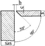
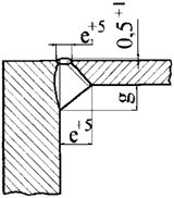
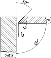
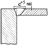
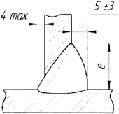
81. At design preference shall be given to the types of welded connections given in the Appendix N 5 to these Rules.
Categories of welded joints not stipulated herein may be used subject to assurance of strength and compliance with requirements of federal rules and regulations in the field of atomic energy use regulating control of metal of the equipment and pipelines of nuclear power installations at production and installation.
82. Smooth transition <1> from one component to another shall be ensured in butt weld joints of components with different nominal wall thickness. Specific forms of the above transition shall be established in engineering (design) documentation, proceeding from requirements of strength calculation and performance of control by the methods provided by federal rules and regulations in the field of atomic energy use regulating control of metal of the equipment and pipelines of nuclear power installations at production and installation.
--------------------------------
<1> Geometric dimensions of the smooth transition shall be assigned in each case in accordance with the requirements of the engineering documentation.
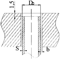
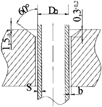
83. When preparing pipes of one nominal diameter with the same nominal wall thickness for butt-welded joints with one-sided cutting of edges, if required by the engineering documentation, calibration (boring or expansion) of the pipe ends to a given internal diameter should be performed.
84.Edges prepared for welding (surfaces for overlaying) and the adjacent surfaces of parts must be cleaned of surface contamination (in case of welding of titanium alloys - cleaned of tarnishing traces, as well). The width of the specified areas shall be not less than 20.0 mm at preparation of parts for arc welding (surfacing) and not less than 50.0 mm - at preparation for electroslag welding.
85. The edges of aluminum alloy parts to be welded must be cleaned mechanically or chemically prior to assembly.
General assembly requirements
86. All parts and assembly units received for assembly must have marking and (or) accompanying documentation confirming the fulfillment of previous operations. The method of marking shall be determined by the manufacturer (installation or repair organization).
87. Assembly of parts (assembly units) for performance of butt welds with annular seams should be carried out on the assembly and welding equipment or devices that ensure the alignment of the parts (assembly units) to be joined.
88. No tacks shall be allowed at the intersection or interface of two or more joints to be welded.
89. Defective tacks must be removed by machining.
Defective tacks shall be removed by air-arc gouging, subject to subsequent mechanical dressing with the removal of gouging marks and a layer of metal to the following thickness:
a) not less than 1.0 mm - for parts made of austenitic steel or alloy steel with a guaranteed yield strength up to 315 MPa inclusive at a temperature of 20 °C;
b) not less than 2.0 mm - for parts of high-chromium steels or alloy steels with a guaranteed yield strength of more than 315 MPa at a temperature of 20 °C.
90. The surface of the parts in the places of welding of temporary service fasteners should be first cleaned of contamination.
91. Seams of welding of temporary service fasteners shall be located at a distance not less than 60.0 mm from the edges which are subject to welding, at assembly for welding of parts made of carbon and silica-manganese steels - not less than 30.0 mm.
92. It shall not be allowed to increase the dimensions of the metal surfacing parts unless stipulated by repair documentation.
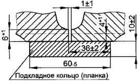
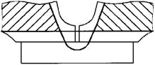
93. In accordance with the requirements of the engineering documentation, assembly for connections of cylindrical parts of equipment and pipelines of groups B and C should be carried out on welded backing elements (rings, ridges).
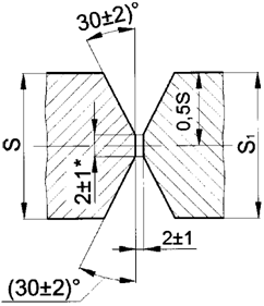
94. In the joints of parts assembled for arc welding with double-sided cutting edges, the displacement of root faces should not exceed 0.5 mm at a nominal root face height of up to 1.0 mm inclusive, half of the nominal root face height at its value of more than 1.0 to 4.0 mm inclusive, and 2.0 mm at a nominal root face height of more than 4.0 mm.
95. Offset (misalignment) of the inner edges in the butt welds with one-sided cutting should not exceed 12% of the nominal thickness of the joined edges, but anyway not more than 0.5 mm.
96. In the butt-welded joints assembled for electroslag welding, the displacement of the edges of parts to be welded must not exceed 2.0 mm.
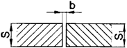
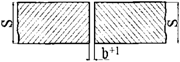
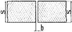
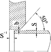
97. In butt-welded joints of parts assembled for arc welding, of the same nominal thickness S, not to be machined after welding in the zone of welds, the permissible displacement of edges (the discrepancy between the surfaces of the parts to be joined) from the side (sides) of welding shall not exceed the standards listed in table No. 1 of these Rules.
Table No. 1
Nominal thickness of the welded components S, mm | Maximum permissible displacement (misalignment) of edges in butt joints, mm | ||
with longitudinal, meridional, chordal and circular seams, as well as with ring seams for welding of bottom plates | with ring seams | ||
at welding of pipes and conical parts | at welding of cylinder-shaped housing parts of sheets or forged pieces | ||
Up to 5.0, inclusive | 0.20S | 0.20S | 0.20S |
Over 5.0 and up to 10.0, inclusive | 0.10S+0.5 | 0.10S+0.5 | 0.25S |
Over 10.0 and up to 25.0, inclusive | 0.10S+0.5 | 0.10S+0.5 | 0.10S+1.5 |
Over 25.0 and up to 50.0, inclusive | 0.04S+2.0 | 0.06S+1.5 | 0.06S+2.5 |
Over 50.0 and up to 100.0, inclusive | 0.02S+3.0 | 0.03S+3.0 | 0.04S+3.5 |
Over 100.0 | 0.01S+4.0, but not exceeding 6.0 | 0.015S + 4.5, but not exceeding 7.5 | 0.025S+5.0, but not exceeding 10.0 |
98. In the joints assembled for welding, the geometric position of the axes of parts must meet the requirements of the engineering documentation.
99. When transporting the assembled parts (assembly units) to the welding site, conditions must be provided to prevent the destruction of the tacks or seams of the welding of temporary service fasteners, as well as damage and (or) contamination of the parts assembled for welding.
Assembly of parts of steels and iron-nickel alloys
100. To perform tacks and welding of temporary service, it is allowed to use arc welding with coated electrodes or argon arc welding.
At assembly of parts for argon-arc or electron-beam welding (including at argon-arc welding of the root part of a seam) tacks should be made by argon-arc welding.
101. Welding of temporary process fasteners should be carried out according to the process documentation containing information on steel grade, shape, size, number and location of these fasteners, qualifications of welders engaged in welding of fasteners, welding materials, methods and modes of welding and heating.
Temporary process fasteners at assembly of parts made of austenitic steels and iron-nickel alloys should be used when the nominal thickness of the parts is not less than 6.0 mm.
102. Tacking and welding of temporary process fasteners at assembling parts made of alloyed and high-chromium steels should be performed with a heated metal in the weld zone according to the mode set for the weld in question, except for welding of tacks of fasteners with austenitic welding materials.
103. Heating at tacking is not mandatory for welded joints, where the root of the seam is made by argon arc welding without heating.
104. At making tacks for assembly of parts (assembly units) welding materials should be applied intended for implementation of welded joints of parts made of steel (alloys) of the relevant grades.
At the assembly of parts made of steels of pearlitic class (except for parts of steel grades 15Kh2MFA-A, 15Kh2NMFA class 1, 15Kh2MFA-A mod. A, 15Kh2MFA-A mod. B, 15Kh2NMFA and 15Kh2NMFA-A, to be joined to each other), the following must be used for tacking:
a) the electrodes of the grades UONII-13/45, UONII-13/45A, UONII-13/45АА and UONII-13/55, TsU-7, TsU-7A and TMU-21U - for manual arc welding with coated electrodes (with the assembly of parts in contact with liquid metal coolant, the electrodes of the first three grades shall only be applied);
b) welding wire of grades Sv-08GS and Sv-08G2S - for argon arc welding.
To perform tack welding at the assembly of parts made of steel of grades 15Kh2MFA-AD, 15Kh2MFA-A mod. A, 15Kh2MFA-A mod. B or 15Kh2NMFA-A to be joined to each other, there should be applied the welding materials given in table No. 2.1 of Appendix No.2 to these Rules.
105. When assembling parts made of pearlitic steels and (or) of high-chromium steels, temporary process fasteners of steel of the same grade as the assembled parts or of carbon steels should be used, and when assembling parts made of austenitic steels, iron-nickel alloys and (or) of two-layer steels (with welding of fasteners to the cladding layer) - of steel of grade 08Kh18N10T.
106. For welding of temporary process fasteners to parts (assembly units) made of steels of pearlitic class without corrosion-resistant surfacing, the same welding materials shall be used as those applied for implementation of tacks in compliance with requirements for heating of base metal. Coated electrodes of grades ZIO-8, TsL-25/1, EA-395/9, TsT-10 and welding wire of grades Sv-10Kh16N25АМ6, Sv-07Kh25N13 shall be applied without heating of the base metal.
107. For welding of temporary process fasteners to parts (assembly units) of high-chromium steels, there should be used:
a) coated electrodes of grades EA-395/9, TsT-10, TsL-25/1, TsL-25/2, ZIO-8 or welding wire of grades Sv-10N16N25AM6 or Sv-07Kh25N13 - for welding of fasteners made of carbon and high-chromium steels to steel parts that do not contain niobium, without heating the base metal;
b) coated electrodes of grades TsL-25/1, TsL-25/2, ZIO-8 or the welding wire of grade Sv-07Kh25N13 for welding of fasteners of high-chromium steel to parts of steel containing niobium, without heating.
108. For welding of temporary process fasteners to parts (assembly units) of austenitic class steels, there should be used:
a) coated electrodes and welding wire approved for welded joints - for welding of austenitic steel fasteners;
b) coated electrodes of grades EA-395/9 and TsT-10 or the welding wire grade Sv-10Kh16N25АМ6 - for welding of fasteners made of carbon steel.
109. For welding of temporary process fasteners to parts of iron-nickel alloys, coated electrodes must be used, or the welding wire allowed for performance of welded joints of parts made of an alloy of the relevant grade.
110. For welding of temporary process fasteners to the cladding layer (corrosion-resistant surfacing) of parts made of two-layer steels, coated electrodes or the welding wire allowed for performance of the top layer of corrosion-resistant surfacing shall be applied.
In the case of the use of carbon steel fasteners on the ends to be welded, a preliminary two-layer surfacing must be performed in compliance with the following requirements:
a) in case of the presence of niobium or titanium in the metal of anti-corrosion overlay, the first surfacing layer shall be made with coated electrodes of grades TsL-25/1 or ZIO-8, or the welding wire of grade Sv-07Kh25N13 and the second layer, with electrodes of grades TsT-15K or EA-898/21B, or welding wire of grades Sv-04Kh20N10G2B or Sv-08Kh19N10G2B;
b) in the absence of niobium or titanium in the metal of corrosion-resistant overlay, the both layers shall be made with coated electrodes of grades TsL-25/1 or ZIO-8, or the welding wire of grade Sv-07Kh25N13.
111. Temporary process fasteners shall be removed by mechanical means. Complete removal of temporary process fasteners with oxygen or air-arc cutting without embedding into the base metal, followed by grinding the surfaces of parts to remove traces of cutting should be performed on parts of carbon and silicon-manganese steels.
On parts of alloyed and high-chromium steels, as well as of austenitic steels, incomplete removal of temporary process fasteners with oxygen (oxygen-flux), plasma-arc or air-arc cutting is allowed. The remaining part of the fastening must be at least 4.0 mm high and shall be mechanically removed.
At removal of temporary process fasteners, incomplete removal of metal of their welding seams is allowed. In the case of welding of temporary process fasteners with austenitic welding materials to parts made of steel of pearlitic class, and of high-chromium steels, and in case of welding fasteners made of carbon steel with these materials to parts made of austenitic steels, incomplete removal of austenitic weld metal should be done from the side not in contact with the working media, and for corrosion-resistant surfacing - from either side.
112. If the clearance exceeds the norms established in Appendix No. 5 to these Rules by not more than half the nominal thickness of the parent metal in the zone subjected to welding of edges, but not more than 10.0 mm, surfacing must be done for the edges (one or two) with coated covered electrodes or welding wire (in case of argon arc welding) of the grades stipulated for the welded joint in question. When surfacing only the root part of the edges of the parts to be joined made of pearlite steel, welding materials used for welding the root part of the seam of this joint should be used. Surfacing should be carried out with heating, if this is provided for the welded joint to be made. After surfacing, the edges are machined to the specified geometric shape. Parts of alloyed and high-chromium steels must be subjected to heat treatment in the intermediate tempering mode (if stipulated) prior to machining of the edges.
Heating during surfacing and heat treatment of the overlaid edges shall not be carried out if the volume of metal deposited on the edges of carbon and silicon-manganese steel parts does not exceed 20 cm3.
113. The remaining backing rings shall be made of the following materials:
a) for welding of parts of materials of the same grade - of the material of the same grade as the welded parts;
b) for welding of parts of steel grades of pearlitic class, as well as for welding of parts made of high-chromium steel of different grades - of the least alloyed steel of compatible grades;
c) for welding of parts of austenitic steels of different grades, as well as for welding of parts of austenitic steels with parts of pearlitic steels or of high-chromium steels with pre-surfacing of edges with austenitic welding materials - of steel of grade 08Kh18N10T, or of austenitic steel of the same grade as one of the welded parts;
d) for welding of parts of steels of pearlitic class with parts of high-chromium steels - of high-chromium steel of the same grade as one of welded details at performance of welded joint with high-chromium welding materials, or of austenitic steels at performance of welded joint with austenitic welding materials;
e) for welding of parts of iron-nickel alloys among themselves and with parts of steels of austenite class - of iron-nickel alloy;
f) for welding of pipes of titanium alloys - of forged or rolled rods of alloys of grades VT 1-00. VT 1-0, or of pipes of alloys of grades PT-1M and PT-7M, regardless of the grade of alloy of the connected pipes; application of forged or rolled rods of alloys of grades PT-3V and 3M is allowed;
g) for welding of parts of titanium alloys, made of sheet metal, bent sheet metal or forged blanks and forgings - of the same types of semi-finished products, for connections of cast and welded structures - of sheet metal or forgings; here, there must be used semi-finished products of alloys of grades VT1-00, VT1-0 and PT-3V, regardless of the grade of the base metal alloy, or combination of alloys.
At the operating temperature up to 450 °C, the remaining backing rings of carbon steel should be used for implementation of welded joints of parts made of steels of pearlitic class, regardless of their grade.
114. After the completion of the assembly for manual arc welding with coated electrodes, parts of austenitic steel and iron-nickel alloys adjacent to the edges of the surfaces should be protected from splashes of molten metal. The width of the protected area shall be not less than 100.0 mm in each side from the edges prepared for welding. At welding of temporary process fasteners to the surfaces of parts made of steels of austenitic class should be used for similar protection. Methods of protection shall be established in the process documentation.
The requirement of the first paragraph of this item is not obligatory if the performed welded joints are subject to subsequent machining with removal in the specified zone of a layer of metal not less than 0.5 mm thick.
Assembly of aluminum alloy parts
115. Welded edges, and adjacent surfaces must be cleaned mechanically or chemically.
116. Tacking must be done by manual or semi-automatic argon arc welding with the same welding materials and in the same modes as welding. Tacks having a silver color and having no pores or cracks are considered to be of proper quality. Defective tacks must be removed by machining.
The length of the tacks and the distance between them should be selected depending on the thickness of the welded parts in accordance with table No. 2 of these Rules.
Table No. 2
Thickness of welded metal, mm | Tack length, mm | Distance between tacks, mm |
from 2.0 to 4.5 | from 20.0 to 25.0 | from 100.0 to 150 |
from 5.0 to 8.0 | from 30.0 to 35.0 | from 150.0 to 200.0 |
from 8.0 to 30.0 | from 40.0 to 50.0 | from 200.0 to 250.0 |
Extreme tacks must be located at a distance of 10.0 - 20.0 mm from the edge of the joint.
117. With the nominal thickness of parts not less than 6.0 mm, welding of temporary process fasteners shall be applied in the cases provided by process documentation. The process documentation should contain information about the grade of aluminum alloy, the dimensions, number and location of fasteners, on welding materials, methods and modes of welding.
Temporary process fasteners shall be removed mechanically with obligatory dressing of locations of their welding. Application of abrasive tools at dressing is not allowed. Damage to the surface bringing the thickness beyond the minus tolerance of metal shall not be permitted.
Capillary inspection (or visual inspection using a magnifying glass with 4-7 magnification factor) shall be carried out in the zones of welding of fasteners made of alloys of grades AB and SAV1after prior dressing of the surface to a roughness of not more than Ra 5 microns (Rz 20 microns) .
118. In the butt joints assembled for welding, the offset of inner edges must not exceed 10% of the thickness of the material along the entire length of the joint (but not more than 0.6 mm) or up to 15% of the thickness of the material (but not more than 1.2 mm) in areas with a length of up to 20% of the length of the seam.
119. Parts intended for the manufacture of pipelines should be stored in a package after cleaning and assembly operations. The shelf life prior to welding shall not exceed 3 days.
Assembly of titanium alloy parts
120. The edges and adjacent surfaces must be degreased after dressing. Welding of temporary process fasteners and lead-out strips and tacks must be implemented with the same welding materials as the main seam with the obligatory protection of the reverse side by blowing with a protective gas. Tacks must be of silver color.
Temporary process fasteners welded to sheet structures must be removed by gas cutting. The cutting line must be at least 10.0 mm away from the surface of the structure.
Edges of pipes and parts intended for the manufacture of pipelines should be stored in a package after dressing and assembly operations. The shelf life of assembled pipe joints shall not be more than 5 days (no more than 36 hours, if the parts were etched).
VI. Welding
General requirements
121. Welding of parts (assembly units) should be carried out according to the process documentation. Welding modes for welded joints are given in Appendix No. 6 to these Rules. The process documentation for welding must establish:
a) welding (surfacing) methods;
b) welding conditions as applied to the implementation of specific welded joints;
c) requirements to welders' qualifications;
d) types of welded joints performed;
e) type and polarity of welding current;
f) welding equipment in use;
g) combinations of grades of base and welding (surfacing) materials;
h) the necessity, techniques and modes of prior and accompanying heating at welding (surfacing);
i) spatial positions of welding (surfacing);
k) the grade and diameter of the electrode and (or) wire, the width, thickness and grade of the tape;
l) requirements for the preparation and baking of welding materials;
m) materials, methods and modes of performance of tacks or instructions on welding of temporary process fasteners;
n) the procedure for laying beads and layers of the seam and overlays;
o) types of heat treatment of welded joints and overlaid parts (if any));
p) gas protection requirements (for argon arc welding);
q) conditions of exposure of welded joints (overlaid parts) from the end of welding (surfacing) to the beginning of heat treatment;
r) methods and scope of operational control of welding (surfacing).
122. For the implementation of welded joints of parts made of steel and iron-nickel alloys, the following welding methods must be applied:
a) automatic submerged arc welding;
b) manual arc welding with coated electrodes;
c) automatic, semi-automatic and manual argon arc welding with consumable and non-consumable electrode;
d) electroslag welding;
e) electron beam welding in vacuum;
f) diffusion welding for steel and zirconium pipe joints.
Argon arc welding shall be carried out in the environment of the protective gases specified in Appendix No. 2 to these Rules.
Semi-automatic welding in gaseous carbon dioxide with welding wire of grade Sv-08G2S should be used to perform welded joints of category III in parts of carbon and silicon-manganese steel.
123. It is allowed to use two or more welding methods from among the aforesaid to perform a single welded joint (combined welding).
124. Welding (surfacing) must be carried out in conditions that protect the welding site from precipitation, moisture, drafts and other impacts that affect the quality of welding.
Welding (surfacing) in the manufacture of equipment and assembly units of pipelines, as well as the implementation of welded joints of categories I, In, II, IIn during installation is not allowed at ambient temperatures below 5 °C.
Welded joints of category III on equipment and pipelines during installation must be carried out at an ambient temperature not lower than minus 15 °C.
The ambient air temperature, at which welding (surfacing) shall be performed during the repair of equipment and pipelines is set in the process regulations by the operating organization.
125. At ambient temperatures below 5 °C, welding (surfacing) of parts made of pearlite and high-chromium steels must be carried out with additional or enhanced heating. For non-heated welds, the minimum prior and accompanying heating temperature must be at least 50 °C (additional heating). For welded joints with mandatory heating, the minimum heating temperature must be increased by 50 °C (enhanced heating).
126. Requirements to heating at welding (surfacing) are given in Appendix No. 7 to these Rules.
127. Before being subjected to welding (surfacing), the parts of austenitic class assembled for welding must be degreased.
128. The root part of the seam should make no more than 30% of the nominal thickness of the welded parts (the design height of the fillet weld), but not more than 20.0 mm.
129. At the performance of multiple-pass weld seams and overlays after the application of each bead, the seam surfaces and the dressing edges should be cleaned of slag, splashes of metal and visually examined for cracks, unacceptable slag or tungsten inclusions, pores, irregularities and other defects. The results of the control must comply with the requirements of federal rules and regulations in the field of atomic energy use regulating the control of metal of equipment and pipelines of nuclear power installations at the manufacture and installation. The defects must be removed mechanically before welding can be resumed.
130. All of the shrinkage holes (craters) must be brought to removable allowances of parts (or to mounting straps), or filled.
131. Welding of fillet seams, which, according to engineering documentation, are subject to tightness requirements, shall be carried out in at least two layers.
132. Partial or complete removal of the root part of the weld before welding on the second side should be performed at two-sided welding (including the implementation of the back-up weld).
A double-sided welding joint (or a single-sided weld with the root pass) must be performed with alternate cutting the edges and welding on one side, followed by cutting and welding on the other side.
At two-way welding of parts made of austenitic steel and iron-nickel alloys, the beads facing the working media must be the last to be made.
133. Welding of multi-pass welds of austenitic steels and iron-nickel alloys must be stopped after each pass to cool the metal to a temperature not exceeding 100 °C.
For welding austenitic steels with a ferritic phase content of 4 - 8%, a periodic temperature increase up to 250 °C is allowed.
134. After welding, the weld surface and the surface of the adjacent area of the base metal must be cleaned of slag and metal splashes to the width required for subsequent inspection.
135. Manual arc welding (surfacing) with coated electrodes with rods of austenitic steel should be performed in narrow beads with a width of not more than three diameters of the electrodes used.
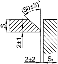
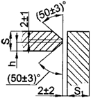
136. Welding of the root portion of the seam of welded joints of parts made of steel grade 08Kh18N12T and iron-nickel alloys as well as pipes made of carbon steel with a nominal wall thickness of 12.0 mm must be performed with application of filler wire.
Welding of parts made of steels of different structural classes
137. Welding materials for performance of welded joints of parts made of steels of different structural classes, including for preliminary surfacing of edges, shall be applied according to requirements of tables N 2.2, 2.4, 2.6 and 2.8 of Appendix No. 2 to these Rules.
138. At welding of parts made of austenitic steel with parts made of carbon and silicon-manganese steels with a nominal thickness of more than 10.0 mm, the edges of parts made of carbon and silicon-manganese steels should be subject to prior surfacing, the thickness of which after machining should be:
a) 6.0 +/- 2.0 mm - for manual arc welding with coated electrodes and argon arc welding;
b) 9.0 +/- 2.0 mm - for automatic submerged arc welding.
Manual arc welding with coated electrodes and argon arc welding on edges deposited for automatic submerged arc welding is allowed.
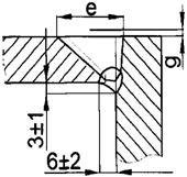
139. At welding of parts of austenitic steel with parts of alloyed and high-chromium steels with a nominal thickness of more than 6.0 mm, the edges of parts of alloyed and high-chromium steels should be subject to prior surfacing, the total thickness of which after machining should be 9.0 +/- 2.0 mm at the thickness of the first layer 3.0 +/- 1.0 mm.
140. The need for prior surfacing of edges at performing fillet, T-shaped and lap welds of carbon and silicon-manganese steel with parts of austenitic steel shall be determined by the calculated height of the fillet seam (instead of the nominal thickness) in accordance with the requirements of paragraph 138 of these Rules.
141. At automatic submerged-arc welding of parts made of steels of pearlitic class with parts of high chromium steels, the edges of parts made of steels of pearlitic class must be subjected to prior surfacing with coated electrodes intended for welding of parts made of high-chromium steel. The above surfacing shall be carried out in at least three layers and have the overall thickness after machining not less than 7.0 mm.
142. For welding at installation and repair of pipes of steels of different structural classes, in case of absence of prior surfacing on their edges made by the manufacturing organization, special factory-made adapters shall be applied.
An adapter is an assembly unit welded of two pipe segments, each of which must correspond to the steel grades of the pipes to be connected. Application of the above adapters shall be provided by engineering documentation.
143. At intersections of seams of austenitic and pearlite welding materials, the welding with pearlite materials must be the first to be carried out.
144. The width of the surface of the metal of the weld or overlay applied at prior surfacing made with electrodes of the grade EA-395/9, TsT-10 or welding wire of the grade Sv-10Kh16N25AM6, which faces the water, water-steam or steam medium of the coolant, shall not exceed 7.0 mm.
Welding of parts of two-layered steels
145. When preparing parts of two-layer steels for welding, the cladding layer in areas adjacent to the edges subject to welding (from the side of their opening), and the areas of application of fillet welds, must be removed, unless otherwise stipulated in this subsection.
The width of the zone of removal of the cladding layer shall be not less than 5.0 mm for manual arc welding with coated electrodes and argon arc welding and not less than 10.0 mm for automatic submerged arc welding. For fillet and t-shaped joints, the area of removal of the cladding layer needs to extend beyond the fillet weld for not less than the specified width values.
For welded joints, the basic layer of which made of pearlite steel is subjected to ultrasonic and (or) radiographic control prior to the application of the cladding layer, the width of the area of removal of the cladding layer must be such that the above control would be possible.
146. When performing welded joints with the removal of the cladding layer, the welding of the basic layer of pearlite steel shall be carried out first, and then welding (surfacing) of the cladding layer.
147. Welding of the basic layer should be carried out with welding materials designed for welding of parts without a cladding layer.
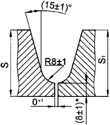
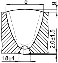
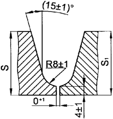
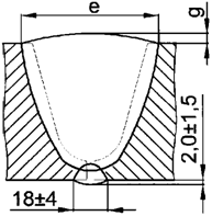
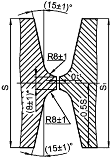
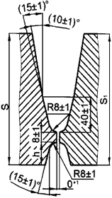
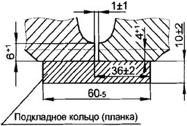
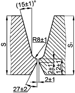
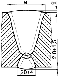
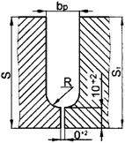
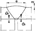
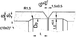
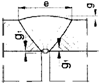
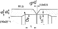
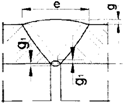
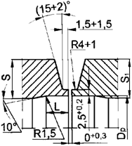
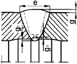
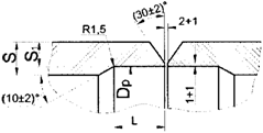
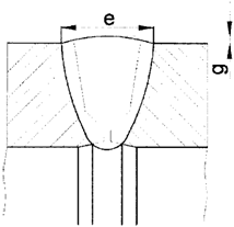
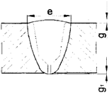
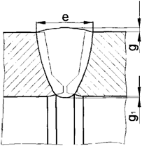
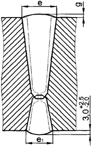
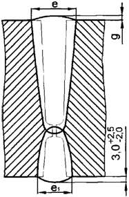
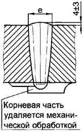
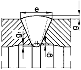
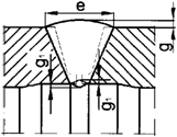
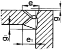
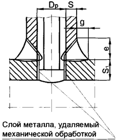
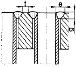
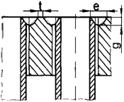
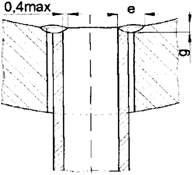
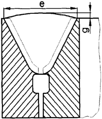
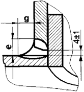
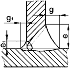
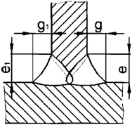
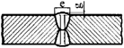
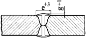
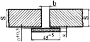
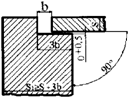
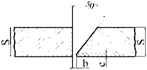
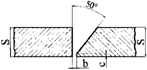
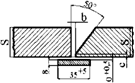
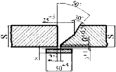
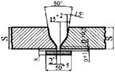
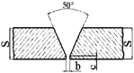
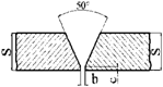
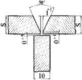
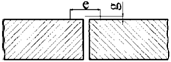
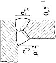
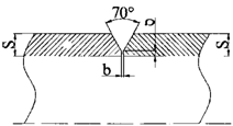
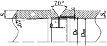
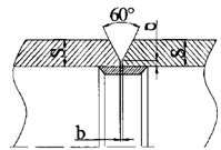
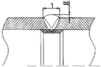
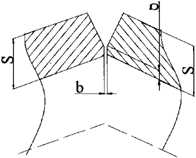
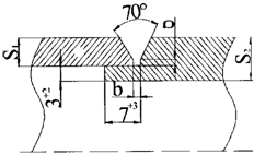
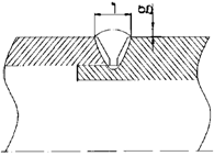
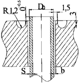
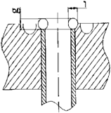
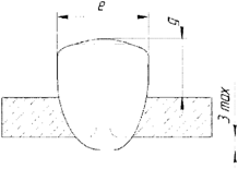
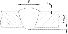
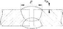
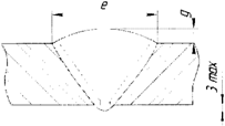
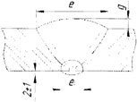
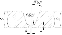
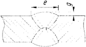
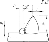
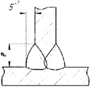
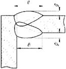
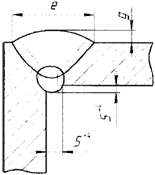
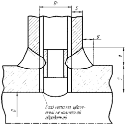
148. Welding (surfacing) of the cladding layer on the seam zone of welding of two-layer steels includes the surfacing of separating and protective surfacing (figure 1).
149. The separating surfacing must be performed with coated electrodes of grades EA-23/15, TsL-25/1 or ZIO-8, welding wire of grade Sv-07Kh25N13 (in case of argon arc welding), welding tape of grades Sv-07Kh25N13, Sv-07Kh25N13А Sv-02Kh23N15 in combination with fluxes of grades OF-10, OF-40, FTs-18 (for automatic submerged surfacing). The dimensions of the welded joint elements shall correspond to those shown in figure 1.
Removing the weld reinforcement should not lead to contact between the separating surfacing and the medium.
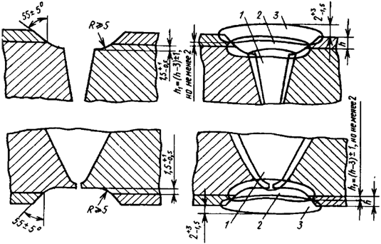
Figure 1. The arrangement of dressing and implementation of welded
joints of parts of two-layered steels:
1 - weld seam;
2 - separating surfacing;
3 - protective surfacing;
150. Protective surfacing must be carried out in at least two layers with the following welding (surfacing) materials:
a) if the welded joint is not subject to heat treatment - with welding materials specified in paragraph 149 of these Rules, or with coated electrodes of grades EA-400/10U, EA-400/10T, TsT-26, TsT-26M, EA-898/21B, TsT-15K, TsL-25/2, or welding wire of grades Sv-04Kh19N11М3, Sv-04Kh20N10G2B Sv-08Kh19N10G2B (in case of argon arc surfacing), or with welding tape of grades Sv-04Kh19N11М3, Sv-04Kh20N10G2B, Sv-08Kh19N10G2B in combination with the flux of grades OF-10, OF-40 or FTs-18 (for automatic submerged surfacing);
b) if the welded joint is subject to heat treatment - with coated electrodes of grades EA-898/21B or TsT-15K, or welding wire of grades Sv-04Kh20N10G2B, Sv-08Kh19N10G2B (in case of argon arc surfacing), or with welding of grades Sv-04Kh20N10G2B, Sv-04Kh20N10G2BA or Sv-08Kh19N10G2B, in combination with the flux of grades OF-10, OF-40 or FTs-18 (for automatic submerged surfacing).
151. Protective and separating surfacing by manual arc welding with coated electrodes should be carried out in separate longitudinal beads with a width of not more than three diameters of the rod of the electrode used.
152. Welding of parts with the rated thickness of the base layer (for fillet and t-welds with the design height of fillet weld) of carbon steel and silico-manganese steels to 36.0 mm inclusive, and of alloyed steel up to 6.0 mm inclusive, should be performed with coated electrodes of grades EA-855/51, EA-32/53 or welding wire of grades Sv-03Kh15N35G7М6B, Sv-03Kh20N65G5М4B3V (in case of argon arc welding) throughout the thickness from either side without removing the cladding layer.
If the metal of the cladding layer does not contain niobium and the welded joint is not subject to heat treatment, welding of the base layer with a thickness of not more than 10.0 mm should be performed with coated electrodes of grades EA-395/9 or TsT-10, or welding wire of grade Sv-10Kh16N25AM6 (with argon arc welding) to a level that overlaps the line of fusion with the cladding layer by not less than 1.0 mm, and the separation and protective surfacing - with coated electrodes of grades EA-400/10U, EA-400/10T, TsT-26, TsT-26M or welding wire of grade Sv-04Kh19N11M3 (at argon arc surfacing) in not less than two layers.
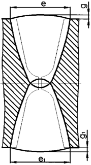
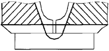
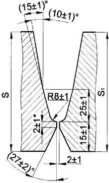
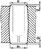
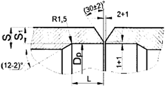
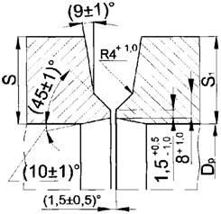
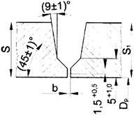
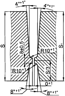
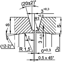
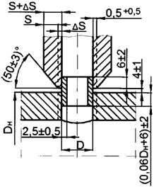
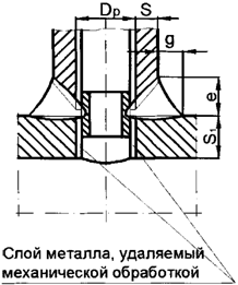
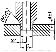
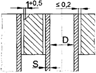
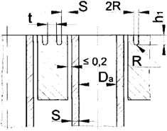
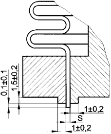
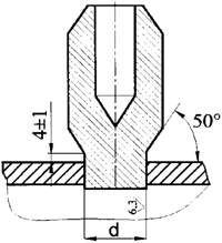
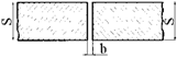
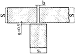
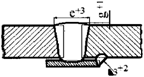
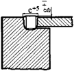
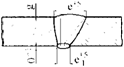
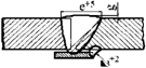
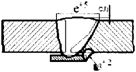
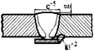
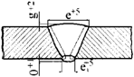
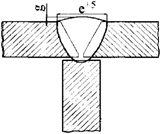
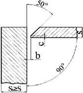
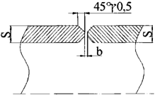
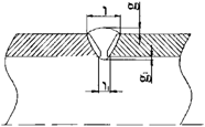
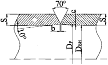
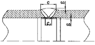
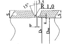
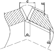
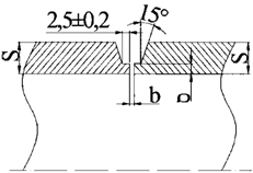
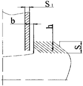
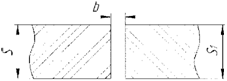
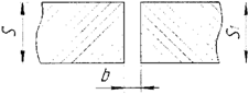
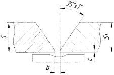
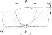
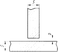
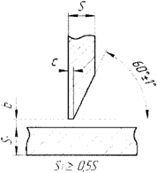
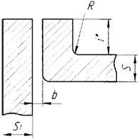
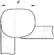
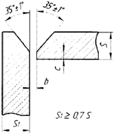
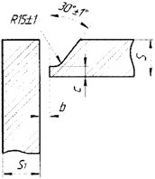
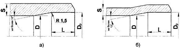
153. One-sided welded joints not accessible for welding from the side of the cladding layer shall be carried out without removing the cladding layer with prior surfacing of edges according to figures 2 and 3.
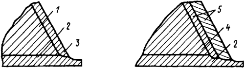
Figure 2. Arrangement of performance of prior
surfacing of parts of two-layered steels
with a cladding layer containing no niobium:
1 - carbon or silica-manganese steel;
2 - cladding layer;
3 - uniform surfacing;
4 - alloyed steel;
5 - double surfacing
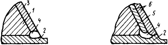
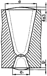
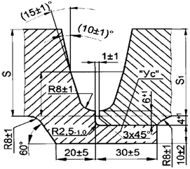
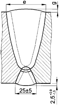
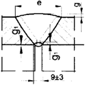
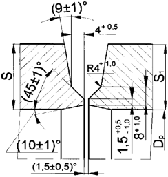
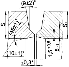
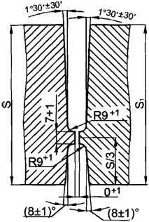
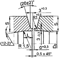
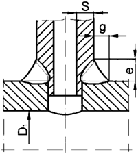
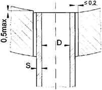
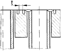
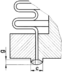
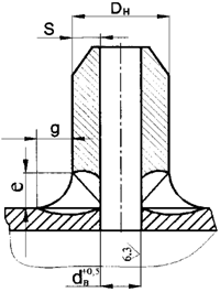
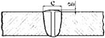
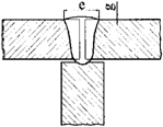
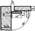
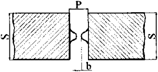
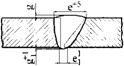
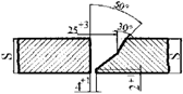
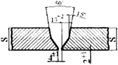
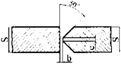
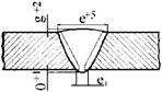
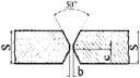
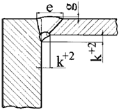
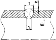
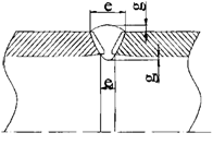
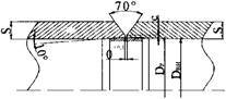
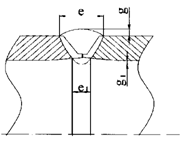
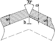
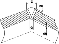
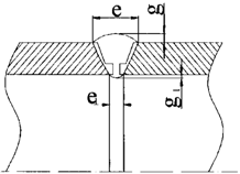
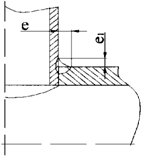
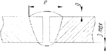
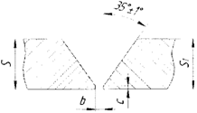
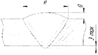
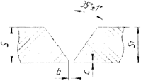
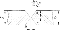
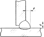
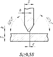
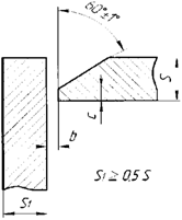
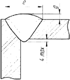
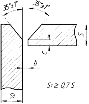
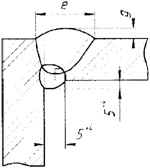
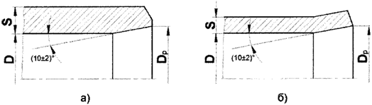
Figure 3. Arrangement of performance of prior
surfacing of parts of two-layered steels
with a cladding layer containing niobium:
1 - carbon or silica-manganese steel;
2 - cladding layer;
3 - uniform surfacing;
4 - separating bead;
5 - alloyed steel;
6 - double surfacing;
If the metal of the cladding layer contains niobium, a separation bead must be made (figure 3), excluding direct contact of the cladding layer with the metal of the prior surfacing on the edges. The separation bead must be made with coated electrodes of grades TsL-25/1 or ZIO-8 or the welding wire of grade Sv-07Kh25N13 (for argon arc welding).
The thickness of the first layer and (or) the total thickness of the prior surfacing should correspond to the same parameters used for welding of steel parts of different structural classes.
154. After prior surfacing heat treatment shall be performed of parts in the area of surfacing (if any), as well as subsequent machining.
155. Welding of parts with surfaced edges should be performed with welding materials as per table No. 2.4 N of appendix No. 2 to these Rules.
156. At welding of parts of two-layer steels with parts of pearlitic steels, the cladding layer shall be removed, after which the welded joint shall be made with welding materials intended for welding parts of steel of the corresponding grades, with the restoration or without subsequent restoration of the cladding layer.
157. At welding of parts of two-layer steels with parts of high-chromium steels, the removal shall be carried out of the cladding layer, after which the welded joint shall be made with welding materials intended for welding parts of steel of the corresponding grades, and the subsequent surfacing of the cladding layer.
158. At welding of parts of two-layer steels with parts made of austenitic steels, the edges of parts of two-layer steels shall be subjected to prior surfacing, and then making the weld joint.
159. Welding to the cladding layer of parts of two-layer steels, protective shirts, as well as parts that are not loaded with pressure, should be performed without removing the cladding layer where they overlap the fillet welds, if the design height of the fillet weld does not exceed 8.0 mm. In this case, the cladding layer shall be considered as austenitic steel.
Electroslag welding
160. Parts made of silicon-manganese and alloy steels, as well as high-chromium steels should be supplied to electroslag welding after complete heat treatment (normalization or quenching followed by tempering). Before the beginning of electroslag welding of parts of two-layer steel, some of the cladding layer shall be removed on the width sufficient for installation of water-cooled sliders and plates.
161. Electroslag welding of a welded joint shall be carried out without interruption.
In the event of a forced break, the welding must continue after removal of the weld area with a shrink hole. Removal of the specified section of the seam when welding parts of alloy steels shall be carried out after the prior tempering of the made part of the welded joint.
At welding of parts made of austenitic steels in the case of the removal of the seam section with a shrink hole after performance of the welded joint, austenization shall be required to be held.
162. At performance of welded joints with ring seams of parts made of steels of pearlitic class, after welding 1/3 of the perimeter of the joint, the initial portion of the seam shall be removed with oxy-acetylene, mechanical or plasma cutting or air-arc gouging. The temperature of the metal in the zone of oxygen-acetylene or plasma cutting or air-arc gouging of welded joints of alloy steel parts should not be lower than 200 °C. The cut edges and the adjacent seam surfaces and the base metal should be cleaned of burrs and scale.
Argon arc welding
163. At welding pipes and other cylindrical parts of austenitic steels, high-chromium steels and iron-nickel alloys, the reverse side of the welded seam must be protected during the performance of the first two layers by blowing the shielding gas.
To reduce gas consumption, it is allowed to install removable plugs in the welded parts to create a chamber of the required volume. Protection of the root of the seam is provided by passing gas through the chamber in a volume equal to 4 - 5 times the volume of the chamber before welding, and then blowing gas during the performance of the first two layers of the seam.
Welding of aluminum alloy parts
164. The following methods of welding in a shielding gas environment are used to perform welded joints:
a) manual welding with non-consumable electrode with filler material (including compressed arc);
b) automatic welding with non-consumable electrode with filler material (including compressed arc);
c) automatic welding with consumable electrode (including pulsed arc welding);
d) semi-automatic welding with consumable electrode (including pulsed arc welding);
It is allowed to use two or more welding methods to perform a single welded joint (combined welding).
165. Manual welding with a non-consumable electrode must be performed with alternating current. In the case of compressed arc welding with water-cooled electrodes, welding must be carried out at reverse polarity direct current.
166. Automatic welding with a non-consumable electrode must be carried out on assembly and welding stands with a forming pad.
167. Semi-automatic and automatic welding with a consumable electrode must be carried out with direct current of reverse polarity.
168. At an air temperature below 0 °C, the welding work in the installation conditions must be carried out with drying of the welded edges at a width of 50.0 - 60.0 mm from the seam axis by electric heating or by heating with the flame of a gas burner to 100 - 120 °C.
The heating temperature of the edges must be controlled with a contact thermoelectric, infrared or laser thermometer (pyrometer).
169. T-joints, for which requirements are imposed to the depth of penetration, and butt joints should be performed in a two-sided seam.
Before applying the seam on the reverse side, the root of the seam of the first pass to the pure metal must be removed mechanically to form a groove. The opening angle of the groove edges should be 60+10°, and the radius of curvature of its bottom - not less than 3.0 mm. The roughness of the groove surface should not exceed Ra 10 microns (Rz 40 microns). The use of abrasive tools or liquid coolant shall not be allowed.
170. Welding of butt joints shall be performed in a one-sided seam according to one of the following options:
a) on a removable pad of austenitic steel or copper with a groove for the formation of the root of the seam; the shape and size of the groove shall be established by process documentation;
b) in the cases stipulated by engineering documentation, the remaining pad made of aluminum or its alloys of the same grade as one of the welded parts shall be used;
c) without fixture, with back forming of seam;
d) with formation of a bulge from the side of the root part, its height exceeding the values established in Appendix N 5 to these Rules, with backup welding without filler wire.
171. When performing T-joints with structural incomplete penetration, the value of the non-penetration shall be determined by the amount of root face of the edge of the welded element.
172. When performing T-joints with single-or double-sided dressing of edges, the first pass must be performed with the provision of penetration and removal of the root of the seam mechanically, and the following one - with aiming alternately at the leg and the wall, to ensure the required size and shape of the seam.
173. The beginning and the end of the seam must be performed on service plates of aluminum alloys. The thickness of the plates, their shape and dimensions shall be specified in the process documentation. In case of an allowance of not less than 50.0 mm along the length of the edges to be welded, welding shall be carried out without service plates. In the absence of service plates, the end of the seam must be brought to the previously performed section of the seam, with the crater to be filled.
174. At double-sided welding of pipes the root pass must first be welded from the inside (backup seam).
175. Depending on the size of pipes, structural elements of edge preparation, welding method, shielding gas and ambient temperature, non-cooled, cooled and heated removable pads shall be used.
It is allowed to use a fixture for assembly and calibration of joints of pipes for welding as a pad.
176. At welding of pipe joints without welding and without pad, the shielding gas must be blown into the inner cavity of the pipes, and the ends of the edges and the adjacent inner surfaces with a width of at least 5.0 mm must be degreased and protected immediately before welding.
Assembly of titanium alloy parts
177. For the implementation of welded joints of parts made of titanium alloys, the following welding methods must be applied:
a) manual argon arc welding with non-consumable electrode;
b) automatic argon arc welding with non-consumable electrode;
c) electron beam welding.
Argon arc welding with a non-consumable electrode must be carried out with direct current of direct polarity, and automatic argon arc welding - with pulsed current.
178. At performing argon arc welding, there must be provided:
a) before welding - quality of gas protection with a "spot" assay;
b) during welding - protection of the front and back sides of the welded joint from oxidation by blowing a shielding gas.
Blowing with a shielding gas must be carried out either with special gas-shielding devices moved along the weld or installed permanently, or by filling the internal volume of the entire structure or a part thereof.
In the manufacture and installation of pipelines, gas protection of the back side of the seam must be carried out by filling the internal volume of the pipeline. Gas protection schemes shall be drawn up for each section of the pipeline and shall be specified in the process documentation.
179. The air temperature during welding should not be lower than +5 °C, and the air flow rate - no more than 0.3 m/s.
Before welding, the purity of the edges to be welded and the surrounding surfaces must be checked. If soiled sites are found, these should be cleaned, degreased and wiped.
180. In case of appearance of tints, welding should be stopped until the causes are identified and eliminated.
Welding of each subsequent pass at performance of multi-pass seams shall begin after cooling of the previous one.
It is not allowed to start and finish welding at places of intersection of seams.
VII. Surfacing
181. For the implementation of overlaid surfaces on parts made of steel and iron-nickel alloys, the following welding surfacing must be applied:
a) automatic submerged surfacing;
b) manual arc surfacing with coated electrodes;
c) automatic, semi-automatic and manual argon arc surfacing with consumable and non-consumable electrode;
d) electric arc and electroslag surfacing with one or two tapes;
e) plasma surfacing.
182. Surfacing of parts should be carried out according to the process documentation. Modes of performance of corrosion-resistant surfacing and cladding of sealing and guiding surfaces are given in Appendix N 6 to these Rules.
The process documentation on corrosion-resistant surfacing and cladding of sealing and guiding surfaces shall establish:
a) grades of steel for surfaced parts;
b) type of surfacing and number of cladded layers;
c) method of surfacing;
d) modes of surfacing in relation to the implementation of specific cladded surfaces;
e) requirements to welders' qualifications;
f) welding (surfacing) equipment in use;
g) grades (combinations of grades) of welding (surfacing) materials;
h) size of surfacing materials;
i) requirements to baking of electrodes and fluxes;
j) requirements for the preparation of the base metal surfaces for surfacing;
k) type and polarity of welding current;
l) spatial positions of surfacing;
m) the magnitude and direction of the electrode displacement relative to the vertical surface of the cladded part (for rotation bodies);
n) the need, method and temperature of prior and accompanying heating during surfacing of the first layer;
o) the procedure for application of beads and layers;
p) thickness of deposited layers and of the cladding as a whole;
q) the need to cool the surface of the previously deposited metal before making subsequent beads (other than the first layer);
r) the procedure for cleaning the surface of the deposited layer and the scheme of removal or filling of craters (for surfacing with tape);
s) conditions of exposure of overlaid parts from the end of surfacing to the beginning of heat treatment;
t) necessity and mode of heat treatment of surfaced parts;
u) information about the methods, scope and evaluation standards for the deposited surface quality control.
183. Homogeneous multi-layer corrosion-resistant surfacing performed with materials that contain no niobium shall only be deposited onto the parts that are not subjected to subsequent heat treatment.
184. The thickness of the homogeneous single-layer corrosion-resistant cladding should be , and that of homogeneous multi-layer cladding - not less than 6.0 mm after the final machining.
185. The thickness of the first layer of the double corrosion-resistant surfacing before the application of the second layer should be . The total thickness of the double-layer anti-corrosion cladding after the final machining should be at least 5.0 mm, that of multi-layer one - at least 7.0 mm.
186. The parts prepared for performance of corrosion-resistant surfacing shall have the marking and (or) the accompanying documentation confirming performance of the previous operations. The method of marking shall be determined by the organization performing surfacing.
187. Parts with welded joints made with electroslag welding should be subjected to heat treatment before surfacing.
188. For performance of corrosion-resistant surfacing, automatic submerged arc surfacing with a welding tape, electroslag submerged surfacing with one or two tapes, manual arc welding with coated electrodes, or argon arc surfacing with wire must be applied.
Automatic submerged surfacing with welding wire must be used in the following cases:
a) for surfacing in the horizontal position of the inner surfaces of nozzles with the vertical arrangement of the nozzle axis with the implementation of the first (lower) ring bead of each layer by manual arc surfacing with coated electrodes and followed by automatic surfacing at an angle of inclination of the wire electrode not more than 45° from the vertical;
b) at introduction of an additional filler wire of the same grade, as the primary welding wire, into the arc.
189. Corrosion-resistant surfacing shall be performed with welding (surfacing) materials specified in table No. 2.5 of Appendix No. 2 to these Rules.
190. Manual arc welding with coated electrodes should be carried out in beads with a width of not more than three diameters of the electrodes used. It is allowed to increase the width of individual beads up to four diameters of the electrode rod, provided that only one bead will be made this way, or the number of such beads will not exceed 5% of the total number of beads made on the overlaid part.
191. At automatic submerged surfacing with tape, each subsequent bead of the layer being made must overlap the previous one by at least 5.0 mm (by width). At manual arc surfacing with coated electrodes and argon arc surfacing, each subsequent bead must overlap the previous one by at least 1/3 of its width.
192. In the process of surfacing, after each successive bead is made, its surface and adjacent areas of the surface of the base and (or) deposited metal must be cleaned of slag, metal splashes and other contaminants and visually checked for defects. Cracks, chips, undercuts and rolls shall be removed mechanically before application of the next bead.
At surfacing with tape, subject to mandatory removal (grinding with abrasive tools with a smooth transition to the previously deposited metal) shall additionally be all the craters (shrink holes) formed during the breaks of the surfacing process. Selected places, except for the second and subsequent layers of corrosion-resistant surfacing, shall be subject to control in accordance with the process documentation, after which they must be filled. The surface of the layer to be surfaced should not have dips or ledges between the beds with a depth (height) of more than 2.0 mm. The dips and ledges of a greater depth (height) should be brought to the specified value by grinding with a smooth transition to the adjacent surface of cladding, or filled with coated electrodes providing the same composition of the deposited metal (or by argon arc surfacing with the use of wire of the same grade). After performance of the specified operations, compliance with requirements of paragraphs 184 and 185 of these Rules shall be provided.
193. After each layer is completed, the surface must be prepared for visual inspection over the entire area of the layer.
194. The surfacing of each subsequent layer should begin after the full implementation of the previous one, with the exception of cases specified in the process documentation.
195. Deposition of the first layer should be performed with preheating according to the requirements of Appendix No.7 to these Rules. In cases where the process documentation provides for a break at performance of the first layer of surfacing, the temperature of the deposited part during the break should not be below 5 °C. Before the resumption of deposition of the first layer of surfacing, heating is necessary.
After surfacing of the first layer, a break is allowed to control the surface quality and thickness of the deposited metal.
196. The procedure for the performance of the second and subsequent layers should ensure a decrease in the temperature of the previously deposited metal in the zone of application of the next bead below 100 °C by the time of approach of the arc.
At automatic surfacing of the second and subsequent layers with a tape of the grade Sv-04Kh20N10G2B, it shall be allowed to increase the specified temperature to 250 °C with periodic control at a distance of 150.0 - 200.0 mm from the arc in the direction of its movement (ahead of the arc along the axis of the bead being deposited). The frequency of control is established by the process documentation depending on the dimensions of the deposited parts.
197. In case of unacceptable irregularities, the surface of the corrosion-resistant surfacing must be machined with an abrasive wheel or by cutting. Depending on the number and location of irregularities, general or local cladding surface treatment should be carried out. After performance of the specified operations, compliance with requirements of paragraphs 184 and 185 of these Rules shall be provided.
Prior elimination of unacceptable irregularities shall be performed by filling with the welding materials intended for the performance of the upper layer of surfacing on the condition that the recovery is carried out within this layer.
198. The corrosion-resistant surfacing on parts made of austenitic steels shall be carried out without preheating with coated electrodes of grades EA-855/51, EA-32/53 or welding wire of grades Sv-03Kh15N35G7М6B, SV-03Kh20N65Г5М4B3V (for argon arc welding or in combination with the flux of grade OF-10 for automatic submerged welding). The number and dimensions of the deposited layers are determined by the process documentation.
199. Requirements to performance of cladding of sealing and guiding surfaces are given in Appendix N 8 to these Rules.
VIII. Heat treatment
The need and types of heat treatment of welded joints and cladded parts are established in Appendix N 9 to these Rules.
IX. Operational control
General requirements
201. Operational control includes:
a) control of preparation and assembly of parts for welding and surfacing;
b) control of welding and surfacing processes;
c) control of heat treatment of welded joints and cladded products.
Operational control shall be carried out in accordance with the process documentation. The scope and frequency of control are established by the organization performing welding (surfacing).
202. The results of each type of operational control shall be recorded in the appropriate control logs.
203. The composition and content of the reporting documentation on the operational control of welding (surfacing) during the repair of equipment and pipelines shall be determined by the operating organization.
Control of preparation and assembly of parts for welding and surfacing;
204. The preparation of parts for welding and surfacing includes the control of the following:
a) availability of marking and (or) documentation confirming the performance of previous operations;
b) the cleanliness of the edges and adjacent surfaces which are subject to welding (surfacing), as well as the areas of the base metal which are subject to nondestructive control;
c) the dimensions of the parts and the shape of dressing of edges, the edge surface roughness;
d) the shape and dimensions of boring or expansion of pipes;
e) the material, shape and dimensions of the backing rings.
205. At assembling of the parts for welding, the following must be controlled:
a) grades and size of the welding materials intended for performance of tacks;
b) securing the parts in assembly fixtures;
c) cleanliness and lack of damage to the edges and adjacent surfaces;
d) heating temperature at performance of tacks;
e) dimensions and location of tack welds and backup welds of temporary fasteners;
f) the size of the gap in the joints after the tacking;
g) the value of displacement of the edges, the break of axes or planes of the parts welded;
h) dimensions of a unit assembled for welding;
i) providing the blowing (if provided by the process documentation).
206. After removal of temporary process fasteners on parts made of alloy steels, austenitic and high chromium steels and on corrosion-resistant surfacing, capillary or magnetic particle inspection of the welding areas shall be performed, or their etching with subsequent inspection through a magnifying glass with a 4 to 7-fold magnification factor.
Control of welding and surfacing processes
207. Before the beginning of the welding (surfacing), the following must be controlled:
a) availability of marking;
b) availability of documents confirming the results of control of welding materials;
c) compliance of humidity of fluxes and the coating of electrodes to the established requirements of the documents on standardization included in the Consolidated List;
d) compliance of the surface of additive materials with the requirements of standardization documents included in the Consolidated List;
e) providing the blowing with shielding gas (if provided by the process documentation).
f) preheating temperatures (if provided by the process documentation).
208. In the course of welding (surfacing), the following must be controlled:
a) welding (surfacing) modes;
b) the sequence of performance of the welds and cladded areas;
c) the ambient temperature at a distance of not more than 2.0 m from the welded or deposited parts;
d) heating temperature;
d) observing the order of application of beads and layers;
e) temperature of metal at welding of parts made of austenitic steels;
g) the thickness of the first layer, the overlap of the rollers and the total thickness of the corrosion-resistant cladding;
h) the quality of the gas shielding of the front and back side of the seam (visually based on tints) - for structures made of titanium alloys.
209. Radiographic control of the root part of the weld joints of categories I and In of parts made of iron-nickel alloys at the nominal wall thickness at the welding site of more than 6.0 mm and of steel at the nominal wall thickness at the welding sites of more than 20.0 mm should be performed. Quality assessment standards shall be adopted as for a completed weld joint.
At butt-welding butt with one-sided dressing of edges, radiographic control should be carried out after filling of the root of the seam.
In the welded connections which are subjected to the subsequent machining with full removal of the seam root, and in cases when no breaks and (or) cooling in the course of welding is allowed, the control is not required.
210. The requirements for the control of the temperature of the prior heating and accompanying heating and the temperature of the metal in the welding zone for austenitic steel parts must be established in the process documentation.
211. After the welding (surfacing), the following must be controlled:
a) availability and correctness of marking of the performed welds and surfacing;
b) temperature conditions of the performed welded joints and cladded surfaces from the moment of the end of welding (surfacing) till the beginning of heat treatment (including conditions of thermal rest, if provided).
Control of heat treatment
212. During heat treatment of welded joints and cladded parts, requirements of the process and engineering documentation must be met as regards:
a) methods and types of heat treatment;
b) thermal equipment used;
c) sequence and order of performance of heat treatment and its individual stages (including preliminary, intermediate and final tempering operations);
d) heat treatment modes (furnace temperature at loading, heating rate, temperature and duration of exposures, cooling rate);
e) the methods and procedures for temperature control of the heating zone of the welded joint and adjacent areas;
e) the conditions providing free expansion of the welded (cladded) parts.
213. For control of the heat treatment modes, thermoelectric converters (thermocouples) with devices for automatic recording of the mode parameters should be used.
214. At out-of-furnace heat treatment, it is allowed to use other means of control of heat treatment modes, providing the required accuracy of temperature measurement.
215. Thermocouples must be installed in the furnace and directly on the heat-treated welded (cladded) parts. The number and location of thermocouples should enable the control of the temperature distribution over the entire volume of the furnace during general heat treatment and control of the heating zones during local heat treatment.
216. In the heat treatment of parts with welded joints of category III, the control of heat treatment conditions should be carried out on the thermocouple installed in the furnace.
217. After the heat treatment, one must record the load number and the furnace number (for furnace heat treatment), the date of the heat treatment and production code (number) of the welded (cladded) part or welded joint.
X. X. Marking of welded joints and cladded parts
218. The weld joints and cladded parts must be marked with brands enabling to identify the name(-s) of the welder(-s) who performed the welding or surfacing. The depth of branding and the size of the brands are stipulated in the process documentation.
219. It is allowed to replace the branding with other methods of marking, ensuring its safety and not impairing the quality and reliability of welded (cladded) parts.
220. In case of removal of brands (marking) at the subsequent machining these shall be restored in the same places.
XI. Elimination of defects
221. All defects found in welded joints and cladded parts during non-destructive testing shall be subject to elimination.
222. Defective areas must be corrected according to the process documentation for the elimination of defects. Filling of recovered areas must be carried out in accordance with the requirements of chapter VI hereof and Appendix No.9 to these Rules.
223. Surface defects should be removed mechanically, ensuring smooth transitions at the recovered sites (abrasive tools, cutting, or cutting followed by grinding).
224. Correction of surface defects without subsequent filling of their recovered sites should be performed:
a) on welded joints - with the remaining thickness of the seam and the base metal not less than the design thickness of the part (assembly unit) at the place of the maximum recovery depth;
b) on corrosion-resistant cladding - with the remaining thickness of cladding not less than the minimum permissible value as per paragraphs 184 and 185 of these Rules, and in the cases which are not regulated by the above paragraphs - not less than the minimum permissible value as per engineering and design documentation.
225. Defects with filling of recovered areas in joints made with arc and electron beam welding on parts of alloy steels which are subject to heat treatment must be eliminated after intermediate or final tempering with the subsequent heat treatment of the repaired product according to the final tempering mode. Repair by welding after thermal rest is not allowed.
226. Internal defects (defective areas) must be removed mechanically (with an abrasive tool, cutting, or cutting followed by grinding).
Defects shall be removed by air-arc or plasma-arc gouging followed by machining of the recovered surface:
a) till complete removal of gouging marks - on the surfaces of recovered areas in welded joints of parts made of carbon or silicon-manganese steels;
b) with the removal of a metal layer with a thickness of not less than 1.0 mm - on the surfaces of samples in welded joints of parts of alloy steels with a guaranteed yield strength at a temperature of 20 °C not more than 315 MPa, or austenitic steels;
c) with the removal of a metal layer with a thickness of not less than 2.0 mm - on the surfaces of recovered areas in welded joints of parts of alloy steels with a guaranteed yield strength at a temperature of 20 °C above 315 MPa, or of high-chromium steels.
227. The shape and size of the prepared recovered areas must allow their filling throughout the volume. The dimensions of recovered areas to be filled (including those penetrating the base metal) are not limited.
228. Defects of welded joints made by electroslag welding should be corrected with arc welding after complete heat treatment (for welded joints of parts made of steels of pearlitic class or of high-chromium steels) or after austenization (in the welded joints of parts made of austenitic steels).
At correction of defects in the above welded joints of parts of alloyed steels which are subject to the subsequent treatment with pressure, the following technology shall be applied:
a) normalization (hardening) and subsequent tempering of the assembly unit with a welded joint made by electroslag welding;
b) recovery of defects;
c) filling recovered areas with carbon steel welding materials;
d) pressure treatment of the assembly unit with heating to a predetermined temperature;
e) normalization (hardening) and subsequent tempering;
f) complete removal of metal deposited with carbon welding materials;
g) filling recovered areas with relevant alloyed welding materials;
h) tempering of corrected weld joint.
The series of the above operations shall be considered as a single correction.
229. Defective weld joints must be corrected by complete removal of the weld, followed by mechanical preparation of the edges and performing the welding joint again.
230. Defects in the assembly butt welds of pipes that are not accessible for repair from the outside should be corrected by cutting the defective weld out and subsequent welding of the pipe segment of the same steel grade into its place. The dimensions of the section shall be determined by the requirements for the distance between the axes of the adjacent annular seams in accordance with Appendix No.5 to these Rules.
231. Defects in the same area of the welded joint or deposited part made of steel and iron-nickel alloys may be corrected no more than three times.
232. The section to be corrected means a rectangle of the smallest area, which can accommodate the recovered area to be filled, plus the adjacent surfaces at a distance equal to three times the width of the above rectangle (figure 4).
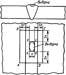
Figure 4. Chart for determination of dimensions
of the section to be corrected:
n - the width of the rectangle;
ABCD - the area to be corrected;
abcd is a rectangle with the smallest area,
which can accommodate the recovered area
233. At correction of defects, the following requirements must be met:
a) when cracks are detected, welding (surfacing) shall be stopped and may be resumed only after the cracks have been removed and measures taken to prevent their occurrence;
b) upon detection of burn-through of the backing ring, the weld joints of pipes inaccessible for welding from the inside must be completely removed and performed again in case of impossibility of repairing the defect without cutting;
c) the number of corrections of the root part of the seam on the same section shall not exceed three;
d) the number of corrections (except for corrections of the root part of the seam) at the depth of recovered areas within the nominal thickness of two layers of the seam shall not be limited or taken into account;
e) the number of corrections (except for corrections of the root part of the seam) at the depth of recovered areas within the nominal thickness of two layers of the seam on the same section must not exceed three.
Welded joints of aluminum alloy parts
234. Surface defects shall be eliminated mechanically with arrangement of smooth transition in recovered areas.
235. In one-sided seams with defects on the reverse side, the weld metal is removed along the entire length of the seam at the same level with the base metal. It is not allowed to penetrate the base metal by a value exceeding the maximum deviation of thicknesses of the welded parts. A smooth transition from the weld to the base metal must be ensured.
236. Internal defects must be removed mechanically. The use of abrasive tools or liquid coolant shall not be allowed.
237. When the thickness of the metal is up to 3.0 mm, the pores, holes and areas of poor penetration shall be corrected without their being removed mechanically first.
In case of tungsten inclusions and cracks it is necessary to remove them mechanically with subsequent filling of the recovered area.
238. The shape and size of recovered areas in the seam metal, including those penetrating the base metal, are not limited and should enable their being filled throughout the volume. At the same time, the width of the seam after filling the recovered area should not exceed the double width of the seam before correction.
239. Defects in pipe butt welds must be corrected by cutting out the defective weld and subsequent welding a pipe section in its place. The dimensions of the pipe section shall be determined by the requirements for the distance between the axes of the adjacent annular seams in accordance with Appendix No.5 to these Rules. Newly made welds shall be subject to full inspection.
240. Defects on the same section of welded joint shall be corrected no more than two times for thermally reinforced alloys of grades AV and SAV1 and no more than three times for thermally non-reinforced alloys of grades ADOO, ADO, AD, AD1, Amg2, Amg3.
Welded joints of titanium alloy parts
241. Defects in the deposited metal of sealing surfaces of parts of titanium alloys shall be removed by machining. The completeness of the removal of cracks shall be checked by capillary control.
242. Defective places shall be corrected by surfacing on the heated part with the same filler material, which was used for the primary surfacing.
243. For surfacing of sealing surfaces, minor defects in the form of single pores that are discovered after the final machining shall be corrected by overlaying oxidized bars of grade PT-7M without heating the parts or subsequent heat treatment.
244. Defects in the same area of the welded joint or deposited part made of titanium alloys may be corrected no more than two times.
Defect elimination control
245. The recovered areas must be subjected to visual inspection. Recovered areas in welded joints of categories I and In in all cases, as well as those of other categories, when correcting defects like cracks and poor penetration and defects identified during the capillary or magnetic particle inspection, shall be subject to capillary or magnetic particle testing (control by etching is allowed).
The quality (roughness) of the surface of recovered area must meet the requirements of the standardization documents for the appropriate control method included in the Consolidated List.
246. Sections that have undergone correction by welding, after heat treatment (if that was required after correction of defects) of weld joints (or cladded parts) shall be subject to continuous non-destructive testing by all methods provided for the welded joint (cladded part) to be corrected.
247. Control must be implemented:
a) for the entire volume of recovered area to be filled;
b) within the weld joint sections adjacent to the recovered area throughout their width to a distance in each direction along the longitudinal axis of the welded joint not less than 2.5 of the maximum depth of the filled recovered area, but not less than 20.0 mm and not more than 100.0 mm;
c) within the sections of the base metal adjacent to the controlled section of the welded seam and to the edges of the filled recovered area.
The width of the base metal sections must comply with the requirements of federal rules and regulations in the field of atomic energy use regulating the control of metal of equipment and pipelines of nuclear power installations at the manufacture and installation.
On the cladded parts, subject to control shall be the corrected section and the sections adjacent thereto to a width not less than 20.0 mm to each side.
XII. Repair involving use of welding
and surfacing at operation
248. The organization of works on repair of equipment and pipelines with application of welding and surfacing shall provide for:
a) process support of works - preparation of process documentation, means of equipment, including means of control (measurements) and tests;
b) incoming inspection of materials and spare parts used for equipment repair;
c) training of contractors of required qualification, training of contractors on stands and simulators prior to performance of complex and critical work;
d) ensuring the performance of work in accordance with the prepared process documentation;
e) operational and acceptance control of quality of performance of works, acceptance control of the components of the equipment subjected to repair, as well as documentation of control data.
249. Process documentation for repair of equipment and pipelines using welding shall be prepared from standard repair documents, if these are available.
In the absence of standard documentation, process documentation should be developed.
250. The technological impossibility of performance of particular process operations shall be specified in repair documentation.
251. Correction of defects at repair shall be exercised in accordance with the requirements of chapter XI of these Rules.
252. Filling of repaired areas shall be carried out by one of the methods of welding (surfacing) given in paragraphs 122, 164, 177 and 181 of these Rules.
The requirement of this paragraph shall not apply to the repair of surfacing of sealing or guiding surfaces.
253. Heat treatment of repaired areas shall be carried out in accordance with the requirements of paragraph 28 of Annex No. 9 to these Rules.
254. Repair with the use of reinforcing cladding shall only be allowed for pipelines made of austenitic steel of nuclear power installations with channel-type reactors. The technology of performance of the reinforcing cladding shall pass the conformity assessment in the form of certification tests.
255. The control of quality control of reinforcing cladding should be carried out in accordance with the provisions of the methods of the operating organization that have passed the conformity assessment in the form of certification tests.
256. At performance of ultrasonic testing on the surface of reinforcing cladding, single inclusions with a maximum size of not more than 1.0 mm are allowed, if their number does not exceed five in any area of 25.0 cm2.
257. At performance of visual inspection of reinforcing cladding, inclusions with the largest actual size up to 0.2 mm shall not be taken into account.
On the surfaces of reinforcing cladding, the height (depth) of the recess between the beads should not exceed 1.0 mm, and scaliness - 0.5 mm.
At automatic arc welding with tape on the surfaces of reinforcing cladding a discrepancy shall be allowed between the heights of two adjacent beads at the places of their conjugation to an amount not exceeding 2.0 mm.
XIII. Certification of welding (surfacing) technology
258. Certification of welding (surfacing) technology shall be performed in accordance with GOST R 50.04.03-2018 "Conformity assessment system in the field of atomic energy use. Conformance assessment in the form of tests. Qualification testing of welding (cladding) technologies" approved by Order of the Federal Agency on Technical Regulation and Metrology dated March 6, 2018 No. 123-St (Standartinform, 2018), in the form of certification tests.
259. Welding (surfacing) must be carried out according to the certified technology.
Appendix 1
to federal rules and regulations
in the field of atomic energy use
"Welding and Surfacing of Equipment and
Pipelines of Nuclear Power
Installations" approved by Decree of the
Federal Service for Environmental,
Industrial and Nuclear Supervision
dated November 14, 2018. No. 554
TERMS AND DEFINITIONS
1. Nuclear power installation is an NPP unit with a water-water reactor, or with a channel-type reactor, or with a fast neutron reactor with a liquid-metal sodium coolant, or an installation with a research reactor of these types.
2. Reference surfacing - surfacing performed to check the characteristics of the deposited metal at the control of welding (surfacing) materials.
3. Reference welding joint is a welded joint performed for metallographic research of welding materials.
4. Reference weld seam is a seam of a welded joint performed for the purpose of checking of characteristics of the seam metal at control of welding materials.
5. The root part of the seam - the weld joint zone adjacent to the root face of the edges with a thickness up to 30% of the total thickness of the weld made, but not more than 20.0 mm.
6. Seam metal - the metal obtained by melting the welding materials in the process of welding and diluted with the base metal due to its melting in the area of welded edges.
7. Surfacing is application of a layer of metal or alloy onto the surface of a product with welding by melting.
7.1. Corrosion-resistant surfacing is the surfacing that protects metal parts (products) from the impact of corrosive medium in the course of operation.
7.2. A layer of corrosion-resistant surfacing is a part of surfacing formed by a number of beads located at the same level from the base metal.
7.3. The thickness of corrosion-resistant surfacing is the distance from the outer surface of the surfacing (from the surface of the first layer) to the zone of its fusion with the base metal.
7.4. Double corrosion-resistant surfacing is the surfacing, the first layer of which is performed with welding (surfacing) materials of one grade (one combination of grades), and the second and subsequent layers - with welding (surfacing) materials of another grade (another combination of grades). Double corrosion-resistant surfacing is classified as two-layer or multi-layer one. Double multilayer surfacing is performed in more than two layers.
7.5. Homogeneous corrosion-resistant surfacing is surfacing performed with welding (surfacing) materials of the same grade (one combination of grades of filler materials and fluxes or shielding gases) throughout the thickness, regardless of the number of layers deposited.
Homogeneous corrosion-resistant surfacing is classified as single-layer or multi-layer one. Homogeneous multilayer surfacing is performed in at least two layers.
7.6. Wear-resistant surfacing is surfacing designed to protect the metal of parts (products) from wear.
7.7. Protective surfacing is surfacing designed to protect the metal of parts (products) from the damaging effects of various factors during operation.
7.8. Prior surfacing is surfacing, which is performed for the preparation for welding of welded joints of steels of different structural classes and steels of the same structural class, but different chemical composition.
7.9. Separation surfacing is surfacing excluding direct contact of dissimilar compositions of deposited metal with each other to prevent the formation of structures prone to hot cracks.
7.10. Sealing surfacing is surfacing performed on the surfaces of flange connectors of equipment and pipelines.
7.11. Reinforcing surfacing is surfacing used in the repair of welded joints and designed to change the stress state of the metal.
8. Overlaid (deposited) metal is metal obtained by melting of welding materials in the process of surfacing (welding) in layers (beads). Also considered as overlaid is the metal of the reference seam performed with prior surfacing of edges in at least three layers with welding materials of the controlled grade.
9. Filler (additive) material is the metal intended for introduction into the weld pool in addition to the molten welding material.
10. Displacement of edges is the misalignment in the levels of the parts or their areas (sections) that have been or will be welded in butt-welded joints.
Appendix No. 2
to federal rules and regulations
in the field of atomic energy use
"Welding and Surfacing of Equipment
and Pipelines of Nuclear Power
Installations" approved by the Decree of the
Federal Environmental,
Industrial and Nuclear Supervision Service
dated November 14, 2018. No. 554
MATERIALS USED FOR PERFORMANCE OF WELDED JOINTS AND OVERLAYS
1. Grades of steel and alloys, the designation of which contains indices for the method of smelting or reworking ("-Sh", "-VD", "-VI", "-ID", "-PD"), are specified in these Rules without indices. The requirements for welding and the welding materials in use do not depend on the method of smelting or reworking of the base metal.
2. Data on materials used for the performance of welded joints of parts made of steels of pearlitic class (except for welded joints of categories In and IIn) are presented in table No. 2.1.of this Appendix.
Table No. 2.1
Grades of steel of parts to be welded | Grades of welding materials in use | Limit temperature for use of welded joints, °C | Note | |||||
coated electrodes for manual arc welding | for automatic submerged welding | welding wire for argon arc welding | for electroslag welding | |||||
wire | flux | wire | flux | |||||
Ст3сп5, 10, 15, 15Л, 20, 20Л, 25Л, 20К between themselves, with steel 22К, with silicon-manganese and alloyed steel | УОНИИ-13/45, УОНИИ-13/45А, УОНИИ-13/55, УОНИИ-13/55АА, ЦУ-5, ЦУ-6, ЦУ-7, ЦУ-7А, ТМУ-21У | Св-08А, Св-08АА, Св-08ГА, | ОСЦ-45, АН-42, АН-42М, АН-348А, АН-348АМ, ФЦ-16, ФЦ-16А, ФЦК-16 | Св-08ГС, Св-08Г2С | Св-10Г2, Св-12ГС, Св-08ГСМТ | ОСЦ-45, АН-8 | 350 | For performance of welded joints of category III of parts of steel of grades Ст3сп5, 10, 15, 15Л, 20, 20Л, 25Л it is allowed to use electrodes of grades МР-3 and АНО-4 |
Св-06А, Св-06АА | АН-42, АН-42М, НФ-18М | |||||||
Sv-08GSMT | АН-42, АН-42М, КФ-19 | |||||||
Св-08ГС | АН-42М, КФ-19, ФЦ-16, ФЦ-16А, ФЦ-22, ФЦ-11 | |||||||
Св-10Г2, Св-08ГА | АН-42М, ФЦ-11, ФЦ-16, ФЦ-16А, КФ-27 | |||||||
Св-10Г2 | ФЦ-22 | |||||||
22К with 22К and steels of grades 15ГС, 16GS, 20GSL, 09Г2С 10ГН2МФА, 15Х2НМФА, 15Х2НМФА-А, 15Х2МФА, 15Х2МФА-А, 15Х2МФА-А mod. А | УОНИИ-13/45, УОНИИ-13/45А, УОНИИ-13/55, УОНИИ-13/55АА, ЦУ-5, ЦУ-6, ЦУ-7, ЦУ-7А, ТМУ-21У | Св-08А, Св-08АА | ОСЦ-45, АН-42, АН-42М, АН-348А, АН-348АМ, ФЦ-16, ФЦ-16А | Св-08ГС, Св-08Г2С | Св-10Г2, Св-12ГС, Св-08ГСМТ | ОСЦ-45, АН-8 | 350 | - |
Sv-08GSMT | АН-42, АН-42М, АН-348А, АН-348АМ, ОСЦ-45 | |||||||
Св-08ГС | КФ-19, ФЦ-11, ФЦ-16, ФЦ-16А, ФЦ-22, АН-42М, 48АФ-71 | |||||||
15ГС, 16GS, 20GSL, 09Г2С with steels 15ГС, 16GS, 20GSL, 09Г2С 10ХСНД, 16ГНМА, 12ХМ, 15ХМ, 20ХМ, 20ХМА, 10Х2М, 12Х1МФ, 15Х1М1Ф in any combination | УОНИИ-13/55, УОНИИ-13/55АА, УОНИИ-13/45А, ЦУ-5, ЦУ-7, ЦУ-7А, ТМУ-21У | Св-08ГС, Св-12ГС | АН-42М, КФ-19, ФЦ-11, ФЦ-16, ФЦ-16А | Св-08ГС, Св-08Г2С | Св-10Г2, Св-12ГС | ОСЦ-45, АН-8 | 350 | Electrodes ЦУ-5 shall only allowed for welding of the root part of the seam |
Св-10Г2, Св-08ГС | ФЦ-22, 48АФ-71 | - | - | - | ||||
09Г2СА-А<1> between themselves, with steel Ст3сп5, 10, 15, 20, 20К, 22К with silicon-manganese and alloyed steel | УОНИИ-13/45АА, УОНИИ-13/55АА, УОНИИ-13/55 <2>, 48Н-37/1 | Св-10НМА-А, Св-08ГНА-А, Св-10НМА-ВИ, Св-08ГНА-ВИ, Св-08ГСА-А, Св-10ГНА, Св-08ГС <3> | ФЦ-16А | Св-10НМА-А, Св-08ГНА-А, Св-10НМА-ВИ, Св-08ГНА-ВИ, Св-08Г2СА-А, Св-10ГНА, ПП-СВП1, Св-08Г2С <3> | - | - | 350 | <1> The minimum temperature of application of steel grade 09Г2СА-А used for making welded joints of parts between themselves shall be minus 50 °C. <2> Electrodes with limited content of S <= 0.012% and P <= 0.012%. <3> Welding wire with limited content of S <= 0.010% and P <= 0.012%. |
10ХСНД with 10ХСНД | УОНИИ-13/45, УОНИИ-13/45А, УОНИИ-13/55, УОНИИ-13/55АА, ТМУ-21У, ЦУ-5, ЦУ-6, ЦУ-7, ЦУ-7А | Св-08ГА, Св-10ГА | ОСЦ-45, АН-348А, АН-348АМ, АН-42, АН-42М | Св-08ГС, Св-08Г2С | Св-10Г2 | ОСЦ-45, АН-8, ОФ-6 | 350 | Electrodes ЦУ-5 shall only allowed for welding of the root part of the seam |
10ХН1М with 10ХН1М and with 10ХСНД | УОНИИ-13/45, УОНИИ-13/45А, УОНИИ-13/55, УОНИИ-13/55АА, Н-20, Н-25 | Sv-08GSMT | АН-42, АН-42М | Св-08ГС, Св-08Г2С | Св-04Х2МА, Св-08ГСМТ | ОФ-6 | 350 | - |
Св-10НМА | АН-42, АН-42М | |||||||
Св-08ГА, Св-10ГА | ОСЦ-45, АН-348А, АН-348АМ | |||||||
Sv-10GN1MA | КФ-27 | |||||||
10Х2М with 10Х2М and with 12Х1МФ, 15Х1М1Ф | Н-10, Н-10АА | Св-04Х2МА, Св-04Х2МАА-ВИ | КФ-16, КФ-16А | Св-04Х2МА, Св-04Х2МАА-ВИ | - | - | 510 | - |
10Х2М with 12ХМ, 15ХМ | Н-10, Н-10АА | Св-04Х2МА, Св-04Х2МАА-ВИ | КФ-16, КФ-16А | Св-04Х2МА, Св-04Х2МАА-ВИ | - | - | 500 | - |
12МХ, 12ХМ, 15ХМ, 20ХМ between themselves and with 20ХМА, 12Х1МФ, 15Х1М1Ф | Н-3, Н-3АА, ЦУ-2ХМ, ЦЛ-38 | Св-08ХМ, Св-08ХМА | АН-42М, КФ-16, ФЦ-11, ФЦ-16 | Св-08ХМ | Св-16Х2НМФТА | ОФ-6 | 350 | For АрДС the wire Св-08ХМ may be used with the content of Si >= 0.22% |
20ХМА with 20ХМА | Н-3, Н-3АА, ЦУ-2ХМ, ЦЛ-38 | Св-08ХМ, Св-08ХМА, Св-08ХМФА, Св-08ХМФА-А | АН-42М, ФЦ-11, ФЦ-16 | - | - | - | 350 | - |
16ГНМА with 16ГНМА and with 12ХМ, 15ХМ, 20ХМ, 20ХМА | ЦЛ-21, ЦЛ-48 | Св-10НМА, Св-10НМА-А, Св-10НМА-ВИ | ФЦ-11, ФЦ-16, ФЦ-16А | Св-10НМА | Св-10НМА | ФЦ-11, АН-8, ОФ-6 | 350 | - |
12Х1МФ, 15Х1М1Ф with 12Х1МФ, 15Х1М1Ф | Н-6, Н-6А, ЦЛ-20, ЦЛ-39, ЦЛ-45 | Св-08ХМФА, Св-08ХМФА-А | ФЦ-11, ФЦ-16, ФЦ-16А, КФ-16 | Св-08ХМФА, Св-08ХГСМФА | - | - | 550 | For АрДС the wire Св-08ХМФА may be used with the content of Si >= 0.22% |
12Х2МФА, 15Х2МФА, 15Х2МФА mod. А, 18Х2МФА in any combinations | Н-3, Н-3АА | Св-10ХМФТУ, Св-10ХМФТУ-А | АН-42М | Св-08ХГСМА | - | - | 350 | For filling of the root part of seam, electrodes may be used УОНИИ-13/45АА, or wire Св-08А (only for parts made of steel of grade 12Х2МФА, 15Х2МФА, 18Х2МФА), Св-08АА under flux АН-42М, 48АФ-71, or Св-08Г2С in argon or in a mixture of gases |
Св-15ХГМТА | 48АФ-71 | |||||||
12Х2МФА-А, 15Х2МФА-А, 15Х2МФА-А mod. А, 15Х2МФА-А mod. Б, 18Х2МФА-А in any combinations | Н-3АА | Св-10ХМФТУ-А | АН-42М | Св-08ХГСМА | - | - | 350 | |
Св-15ХГМТА | 48АФ-71 | |||||||
15Х2НМФА with 15Х2НМФА and with 15Х2НМФА-А | РТ-45А, РТ-45АА, РТ-45Б | Св-12Х2Н2МА, Св-12Х2Н2МАА, Св-12Х2Н2МАА-ВД, Св-12Х2Н2МАА-ВИ | ФЦ-16, ФЦ-16А | Св-12Х2Н2МА, Св-12Х2Н2МАА, Св-12Х2Н2МАА-ВД, Св-12Х2Н2МАА-ВИ | Св-16Х2НМФТА | ОФ-6, ФЦ-21 | 350 | For filling of the root part of seam, electrodes may be used of grade УОНИИ-13/45АА or wire Св-08А (only for parts made of steel of grade 15Х2НМФА), Св-08ААunder fluxes АН-42М, ФЦ-16А |
Св-09ХГНМТА, Св-09ХГНМТАА-ВИ | НФ-18М, ФЦ-16А | Св-09ХГНМТА, Св-09ХГНМТАА-ВИ | ||||||
15Х2НМФА-А with 15Х2НМФА-А and with 15Х2НМФА class 1 | РТ-45АА, РТ-45Б | Св-12Х2Н2МАА, Св-12Х2Н2МАА-ВД, Св-12Х2Н2МАА-ВИ | ФЦ-16А | Св-12Х2Н2МАА, Св-12Х2Н2МАА-ВД, Св-12Х2Н2МАА-ВИ Св-09ХГНМТАА-ВИ | - | - | ||
15Х2НМФА class 1 with 15Х2НМФА class 1 and with 15Х2НМФА | Св-09ХГНМТАА-ВИ | НФ-18М, ФЦ-16А | ||||||
15Х3НМФА with 15Х3НМФА 15Х3НМФА-А | РТ-45Б, Н-23 | Св-09ХГНМТА, Св-09ХГНМТАА-ВИ | НФ-18М, ФЦ-16А | Св-08ХГСМА | - | - | 350 | - |
15Х3НМФА, 15Х2НМ1ФА, 15Х2НМ1ФА-А between themselves and with 15Х3НМФА | Н-23, РТ-45Б | Св-09ХГНМТА, Св-09ХГНМТАА-ВИ | НФ-18М, ФЦ-16А | - | - | - | 350 | - |
15Х3НМФА-А, 15Х2НМ1ФА-А in any combinations | РТ-45Б, Н-23 | Св-09ХГНМТА, Св-09ХГНМТАА-ВИ | НФ-18М | - | - | - | 350 | - |
10ГН2МФА or 10ГН2МФА-А with 10ГН2МФА, 10ГН2МФА-А, 15Х2НМФА, 15Х2НМФА-А | ПТ-30, ЦЛ-59 | Св-10ГНМА, Св-10ГН1МА, Св-10ГН1МА-ВИ | ФЦ-16, ФЦ-16А | СВ-10Г1СН1МА, Св-10ГН1МА, Св-10ГН1МА-ВИ | Св-10ГН2МФА | ОФ-6, ФЦ-21 | 350 | 1. For manual АрДС it shall be allowed to use wire content of Si >= 0.22%. 2. For filling of the root part of seam, electrodes may be used of grade УОНИИ-13/45А, or wire Св-08ГС, or Св-08Г2С in the environment of shielding gases |
10ГН2МФА with 10ГН2МФА and with 15Х2НМФА, 15Х2НМФА-А | ПТ-30, ЦЛ-59 | Св-10ГНМА, Св-10ГН1МА | ФЦ-16, ФЦ-16А | Св-10ГНМА, Св-10ГН1МА | Св-10ГН2МФА | ОФ-6, ФЦ-21 | 350 | 1. For АрДС it shall be allowed to use wire with content of Si >= 0.22%. 2. For filling of the root part of seam, electrodes may be used of grade УОНИИ-13/45А or wire Св-08ГС, or Св-08Г2С in the environment of shielding gases |
10ГН2МФА or 10ГН2МФА-А with 15Х2МФА, 15Х2МФА-А, 15Х2МФА-А mod. А | ПТ-30, ЦЛ-59 | Св-10ГНМА, Св-10ГНША, Св-10ГН1МА-ВИ | ФЦ-16, ФЦ-16А | Св-10ГНМА, Св-10ГН1МА, Св-10ГН1МА-ВИ | - | - | 350 | - |
10ГН2МФА or 10ГН2МФА-А with 15Х3НМФА, 15Х3НМФА-А | ПТ-30, ЦЛ-59 | Св-10ГНМА, Св-10ГН1МА | ФЦ-16, ФЦ-16А | Св-10ГНМА, Св-10ГН1МА | - | - | 350 | - |
10ГН2МФА, 10ГН2МФА-А, 15Х2НМФА, 15Х2НМФА-А, 15Х2НМФА class 1 between themselves and with parts of other pearlitic steels | ЦТ-36, ЦТ-48, ЦТ-48У | - | - | Св-08Н60Г8М7Т, Св-06Х15Н60М15, Св-03Х19Н60М15 | - | - | 350 | Without heat treatment |
3. Data on materials used for the performance of welded joints of parts made of high-chromium steels (except for welded joints of categories In and IIn) are presented in table No. 2.2.of this Appendix.
Table No. 2.2
Grades of steel of parts to be welded | Grades of welding materials in use | Limit temperature for use of welded joints, °C | |||
coated electrodes for manual arc welding | for automatic submerged welding | welding wire for argon arc welding | |||
wire | flux | ||||
08Х13 with 08Х13 and with 06Х12Н3Д, 06Х12Н3ДЛ | ЦЛ-51 | Св-06Х14, Св-01Х12Н2-ВИ | АН-22, ФЦ-19, ФЦК-19 | Св-06Х14, Св-01Х12Н2-ВИ, Св-0Х12Н2МТ-ВИ | 300 |
06Х12Н3Д, 06Х12Н3ДЛ with 06Х12Н3Д, 06Х12Н3ДЛ | ЦЛ-51 | Св-01Х12Н2-ВИ, Св-01Х12Н2У-ВИ | ФЦ-19, ФЦК-19 | Св-01Х12Н2-ВИ, Св-01Х12Н2У-ВИ | 350 |
08Х14МФ with 08Х14МФ | ЦЛ-51, ЦТ-45 | Св-01Х12Н2-ВИ | ФЦ-19, ФЦК-19 | Св-01Х12Н2-ВИ, Св-03Х20Н45Г6М6Б-ВИ | 350 |
05Х12Н2М with 05Х12Н2М | - | - | - | Св-01Х12Н2МТ-ВИ | 350 |
07Х16Н4Б with 07Х16Н4Б | - | Св-09Х16Н4Б, Св-07Х16Н4Б | ОФ-6 | Св-09Х16Н4Б, Св-07Х16Н4Б | 350 |
10Х9МФБ with 10Х9МФБ | ЦЛ-57 | Св-10Х9НМФА, Св-10Х9НМФА-ВИ | ФЦ-16А | Св-10Х9НМФА, Св-10Х9НМФА-ВИ | 550 |
07Х12НМФБ with 07Х12НМФБ | ЭМ-99 | Св-10Х12НМФТ | ФЦ-19 | Св-10Х12НМФТ | 550 |
4. Data on materials used for the performance of welded joints of parts made of steels of austenitic class (except for welded joints of categories In and IIn) are presented in table No. 2.3.of this Appendix.
Table No. 2.3
Grades of steel of parts to be welded | Grades of welding materials in use | Limit temperature for use of welded joints, °C | |||||
coated electrodes for manual arc welding | for automatic submerged welding | welding wire for argon arc welding | for electroslag welding | ||||
wire | flux | wire | flux | ||||
12Х18Н9Т, 12Х18Н9ТЛ, 06Х18Н10Т, 08Х18Н10Т, 12Х18Н10Т, 08Х18Н12Т, 12Х18Н12Т, 10Х17Н13М2Т, 12Х18Н12М3ТЛ in any combination | ЭА-400/10У, ЭА-400/10Т ЦТ-15К, ЦТ-26 ЦТ-26М, ЭА-898/21Б, ЭА-902/14 | SV-04KH19N11M3 | ОФ-6, ОФ-40, ФЦ-17, СФМ-301 | Св-04Х19Н11М3, Св-08Х18Н9Ф2С2, Св-08Х19Н10Г2Б, Св-04Х20Н 10Г2Б | Sv-04Kh19N11M3 | ОФ-6 | 350 <*> |
Св-08Х19Н10М3Б | ОФ-6 | Св-06Х19Н9Т | ОФ-6 | ||||
Св-08Х19Н10Г2Б, Св-04Х20Н10Г2Б | ОФ-6, ОФ-40 | 08Х18Н10Т (plate) | ОФ-6 | ||||
08Х18Н10Т, 12Х18Н10Т with 08Х18Н10Т, 12Х18Н10Т | - | Sv-04Kh19N11M3 | ФЦК-17 | Sv-04Kh19N11M3 | - | - | 350 <*> |
08Х18Н10Т, 12Х18Н10Т with ХН35ВТ | ЭА-855/51, ЭА-32/53 | - | - | Св-03Х15Н35Г7М6Б, Св-03Х20Н65Г5М4Б3В | - | - | 350 <*> |
ХН78Т | ЭА-32/53 | - | - | Св-03Х20Н65Г5М4Б3В | - | - | 550 |
03Х21Н32М3Б with 03Х21Н32М3Б and with 12Х18Н9Т, 08Х18Н10Т, 12Х18Н10Т, 08Х18Н12Т, 10Х17Н13М3Т | ЭА-855/51, ЭА-32/53 | Св-03Х15Н35Г7М6Б, Св-03Х20Н65Г5М4Б3В | ОФ-6, ОФ-40 | Св-03Х15Н35Г7М6Б, Св-03Х20Н65Г5М4Б3В | - | - | 350<*> |
03Х21Н32М3Б with 03Х21Н32М3Б and with 10Х17Н13М3Т | ЭА-855/51, ЭА-32/53 | Св-03Х15Н35Г7М6Б, Св-03Х20Н65Г5М4Б3В | ОФ-6, ОФ-40 | Св-03Х15Н35Г7М6Б, Св-03Х20Н65Г5М4Б3В | - | - | 550 |
10Х17Н13М3Т with 10Х17Н13М3Т | ЭА-855/51, ЭА-32/53 | Св-03Х15Н35Г7М6Б, Св-03 Х20Н65Г5М4Б3В | ОФ-6, ОФ-40 | Св-03Х15Н35Г7М6Б, Св-03Х20Н65Г5М4Б3 | - | - | 550 |
03Х22Н5АМ3 with 03Х22Н5АМ3 | ЭА-127/56 | - | - | Св-02Х22Н9АМ3 | - | - | 250 |
03Х25Н7АМ4 with 03Х25Н7АМ4 | ЭА-127/57 | - | - | Св-02Х25Н10АМ4 | - | - | 250 |
Note. For submerged arc welding of parts made of steel of grade 08Х18Н10Т with application of wire of grade Св-04Х19Н11М3 intended for operation at a temperature not exceeding 200 °C, it shall be allowed to use the flux of grade АН-26 or АН-26С. | |||||||
<*> The limit temperature for use of welded joints shall be 450 °C in case there is no contact with water. |
5. Table No. 2.4 of this Appendix presents information on materials used for performance of welded joints of parts of steels of austenitic class with parts of steels of pearlitic class and high-chromium steels (except for weld joints of categories In and IIn). The maximum temperature of application of materials used for performance of welded joints of parts made of austenitic steels with parts made of steels of pearlitic class and high-chromium steels (except for welded joints of categories In and IIn) shall be 350 °C.
Table No. 2.4
Characteristics of parts to be welded | Grades of welding materials for prior surfacing of edges of parts made of steels of pearlitic class and high-chromium steels | Grades of welding materials for performance of welded seam | |||||||
class (grade) of steel | nominal thickness of parts in the place of welding, mm | coated electrodes for manual arc surfacing | for automatic submerged surfacing | welding wire for argon arc surfacing | coated electrodes for manual arc welding | for automatic submerged welding | welding wire for argon arc welding | ||
tape or wire | flux | wire | flux | ||||||
Austenitic steel with carbon or silico-manganese steel | Up to 10.0, inclusive | - | - | - | - | ЭА-395/9, ЦТ-10 | - | - | Св-10Х16Н25АМ6 |
ЗИО-8, ЦЛ-25/1, ЦЛ-25/2, ЦЛ-25Л | - | - | Св-07Х25Н13 | ||||||
Up to 36.0, inclusive | - | - | - | - | ЭА-855/51, ЭА-32/53 | - | - | Св-03Х15Н35Г7М6Б, Св-03Х20Н65Г5М4Б3В | |
Up to70.0 inclusive<*> | - | - | - | - | ЦЛ-25Л, ЗИО-8 | - | - | Св-07Х25Н13, Св-02Х24Н13 | |
Austenitic steel with carbon or silico-manganese steel | Irrespective of thickness | Homogeneous surfacing (single-layer or multi-layer one) | ЭА-400/10У, ЭА-400/10Т, ЦТ-26, ЦТ-26М | - | - | Sv-04Kh19N11M3 | |||
ЭА-395/9, ЦТ-10 | Св-10Х16Н25АМ6 | ОФ-10, ОФ-40 | Св-10Х16Н25АМ6 | ||||||
ЭА-855/51 | Св-03Х15Н35Г7М6Б | ОФ-6 | Св-03Х15Н35Г7М6Б | ЭА-855/51 | Св-03Х15Н35Г7М6Б | ОФ-6 | Св-03Х15Н35Г7М6Б | ||
Double surfacing | ЭА-400/10У, ЭА-400/10Т, ЦТ-26, ЦТ-26М | Sv-04Kh19N11M3 | ОФ-6, ОФ-40, ФЦ-17, ФЦК-17, СФМ-301 | Sv-04Kh19N11M3 | |||||
First layer | |||||||||
ЭА-395/9, ЦТ-10 | Св-10Х16Н25АМ6 | ОФ-10, ОФ-40 | Св-10Х16Н25АМ6 | ||||||
Second and subsequent layers | |||||||||
ЭА-400/10У, ЭА-400/10Т, ЦТ-26, ЦТ-26М | Св-04Х19Н11М3 (tape) | ОФ-10, ОФ-40, ФЦ-18 | Sv-04Kh19N11M3 | ||||||
Св-04Х19Н11М3 (wire) | ОФ-6, ОФ-40, ФЦ-17, ФЦК-17, СФМ-301 | ||||||||
Austenitic steel with alloyed or high-chromium steel | Up to 6.0, inclusive | - | - | - | - | ЭА-395/9, ЦТ-10 | - | - | Св-10Х16Н25АМ6 |
- | - | - | - | ЗИО-8, ЦЛ-25/1, ЦЛ-25/2 | - | - | Св-07Х25Н13 | ||
- | - | - | - | ЭА-855/51, ЭА-32/53 | - | - | Св-03Х15Н35Г7М6Б, Св-03Х20Н65Г5М4Б3В | ||
Austenitic steel with alloyed or high-chromium steel | Irrespective of thickness | Double surfacing | ЭА-400/10У, ЭА-400/10Т, ЦТ-26, ЦТ-26М | Sv-04Kh19N11M3 | ОФ-6, ОФ-40, ФЦ-17 ФЦК-17, СФМ-301 | Sv-04Kh19N11M3 | |||
First layer | |||||||||
ЭА-395/9, ЦТ-10 | Св-10Х16Н25АМ6 | ОФ-10, ОФ-40 | Св-10Х16Н25АМ6 | ||||||
Second and subsequent layers | |||||||||
ЭА-400/10У, ЭА-400/10Т, ЦТ-26, ЦТ-26М | Св-04Х19Н11М3 (tape) | ОФ-10, ОФ-40, ФЦ-18 | SV-04KH19N11M3 | ||||||
Св-04Х19Н11М3 (wire) | ОФ-6, ОФ-40, ФЦ-17, ФЦК-17, СФМ-301 | ||||||||
Homogeneous surfacing (single-layer or multi-layer one) | ЭА-855/51, ЭА-32/53 | Св-03Х15Н35Г7М6Б, Св-03Х20Н65Г5М4Б3В | ОФ-6 | Св-03Х15Н35Г7М6Б, Св-03Х20Н65Г5М4Б3В | |||||
ЭА-855/51, ЭА-32/53 | Св-03Х15Н35Г7М6Б, Св-03Х20Н65Г5М4Б3В | ОФ-6 | Св-03Х15Н35Г7М6Б, Св-03Х20Н65Г5М4Б3В | ||||||
07Х16Н4Б with 08Х18Н10Т, 12Х18Н10Т | Irrespective of thickness | ЭА-898/21Б | Св-04Х20Н10Г2Б, Св-04Х20Н10Г2БА (tape) | ОФ-10, ОФ-40 | Св-04Х20Н10Г2Б | ЭА-898/21Б | Св-04Х20Н10Г2Б | ОФ-40, ОФ-6 | Св-04Х20Н10Г2Б |
Св-04Х20Н10Г2Б (wire) | ОФ-6, ОФ-40 | ||||||||
06Х12Н3Д, 06Х12Н3ДЛ with 10ГН2МФА | ЦЛ-51 <**> | - | - | - | ЦЛ-51 | Св-01Х12Н2-ВИ, Св-01Х12Н2У-ВИ | ФЦ-19, ФЦК-19 | Св-01Х12Н2-ВИ, Св-01Х12Н2У-ВИ | |
08Х14МФ with 20, 22К | Irrespective of thickness | ЦЛ-51 <***> | - | - | - | ЦТ-45, ЦЛ-51 | Св-01Х12Н2-ВИ | ФЦ-19, ФЦК-19 | Св-01Х12Н2-ВИ, Св-03Х20Н45Г6М6Б-ВИ |
08Х14МФ with 09Г2СА-А | - | - | - | - | - | - | - | Св-03Х20Н45Г6М6Б-ВИ | |
Notes. 1. Heat treatment of dissimilar welded joints is not allowed. 2. At performance of fillet and t-shaped dissimilar welded joints, the need for prior surfacing of the edges of parts made of pearlite or high-chromium steels shall be determined by the design height of the fillet seam and shall be specified in the engineering and process documentation. 3. The need for prior surfacing of edges for performance of fillet and t-shaped welded joints shall be determined by the requirements of engineering and process documentation for welding parts of austenitic steel with the design height of the fillet seam: - up to 10.0 mm inclusive - to parts of carbon and silicon-manganese steel; - up to 6.0 mm inclusive - to parts of alloyed and high-chromium steel. 4. For combined welding methods, the welding materials listed in the same line of the table (separated with horizontal lines) must be used. 5. For performance of welded connections it is allowed to apply grades of steel from table N 2.3 as austenitic steel. | |||||||||
<*> Only at repair of equipment and pipelines in the course of operation. <**> Prior surfacing of edges shall be performed on a part of steel of grade 10ГН2МФА with electrodes of grade ЦЛ-51. <***> With prior surfacing of edges of parts of steel of grades 20, 22К with electrodes of grade ЦЛ-51. |
6. Data on materials used for corrosion-resistant surfacing are presented in table No. 2.5 of this Appendix. The limit temperature for application of materials used for performance of corrosion-resistant surfacing shall be 350 °C.
Table No. 2.5
Characteristics of surfacing | Overlaid layers | Grades of welding (surfacing) materials | Note | ||||
for automatic submerged surfacing | coated electrodes for manual arc surfacing | wire for argon arc surfacing | |||||
based on type | based on the number of overlaid layers | tape or wire | flux | ||||
Homogeneous | Single-layer | - | Св-03Х22Н11Г2Б (tape), Св-03Х24Н13Г2Б, Св-02Х24Н13Г2Б (tape) | ФЦ-18 | - | - | - |
Св-02Х21Н11Г2Б <*> | ФЦК-18 | - | - | - | |||
Св-03Х15Н35Г7М6Б, Св-03Х20Н65Г5М4Б3В | ОФ-6, ОФ-40 | ЭА-855/51, ЭА-32/53 | Св-03Х15Н35Г7М6Б, Св-03Х20Н65Г5М4Б3В | - | |||
Homogeneous | Multi-layer | All | Св-07Х25Н13 (tape) | ОФ-10, ОФ-40, ФЦ-18 | ЗИО-8, ЭА-23/15 or ЦЛ-25/1 (first layer), ЦЛ-25/2 (second and subsequent layers) | Св-07Х25Н13, Св-02Х23Н15 | In the case of heat treatment corrosion resistance of surfacing with the top layer is not provided |
Св-07Х25Н13А, Св-02Х23Н15 (tape) | ОФ-10, ОФ-40 | ||||||
Св-07Х25Н13, Св-02Х23Н15 (wire) | ОФ-6, ОФ-40, ФЦ-17 | ||||||
All | Св-03Х15Н35Г7М6Б, Св-03Х20Н65Г5М4Б3В (wire) | ОФ-10, ОФ-40, ФЦ-17 | ЭА-855/51, ЭА-32/53 | Св-03Х15Н35Г7М6Б, Св-03Х20Н65Г5М4Б3В | - | ||
Double | Double-layer | First | Св-07Х25Н13 (tape) | ОФ-10, ОФ-40, ФЦ-18 | ЦЛ-25/1, ЗИО-8, ЭА-23/15 | Св-07Х25Н13, Св-02Х23Н15 | - |
Св-07Х25Н13А, Св-02Х23Н15 (tape) | ОФ-10, ОФ-40 | ||||||
Св-07Х25Н13, Св-02Х23Н15 (wire) | ОФ-6, ФЦ-17 | ||||||
Second | Св-04Х20Н10Г2Б (tape) | ОФ-10, ОФ-40, ФЦ-18 | ЭА-898/21Б, ЦТ-15 К, ЭА-18/1 0Б | Св-04Х20Н10Г2Б, Св-02Х18Н10Б | - | ||
Св-04Х20Н10Г2БА, Св-02Х18Н10Б (tape) | ОФ-10, ОФ-40 | ||||||
Св-04Х20Н10Г2Б, Св-02Х18Н10Б (wire) | ОФ-6, ОФ-40, ФЦ-17 | ||||||
Double | Multi-layer | First | Св-07Х25Н13 (tape) | ОФ-10, ОФ-40, ФЦ-18 | ЦЛ-25/1, ЗИО-8, ЭА-23/15 | Св-07Х25Н13, Св-02Х23Н15 | - |
Св-07Х25Н13А, Св-02Х23Н15 (tape) | ОФ-10, ОФ-40 | ||||||
Св-07Х25Н13, Св-02Х23Н15 (wire) | ОФ-6, ОФ-40, ФЦ-17 | ||||||
Second and subsequent layers | Св-04Х20Н10Г2Б, Св-08Х19Н10Г2Б (tape) | ОФ-10, ОФ-40, ФЦ-18 | ЭА-898/21Б, ЦТ-15 К, ЭА-18/1 0Б | Св-04Х20Н10Г2Б, Св-08Х19Н10Г2Б, Св-02Х18Н10Б | |||
Св-04Х20Н10Г2БА, Св-08Х 19Н10Г2БА Св-02Х18Н10Б (tape) | ОФ-10, ОФ-40 | ||||||
Св-04Х20Н10Г2Б, Св-08Х 19Н10Г2Б, Св-02Х18Н10Б (wire) | ОФ-6, ОФ-40, ФЦ-17 | ||||||
<*> Electroslag surfacing with tape of grade Св-02Х21Н11Г2Б shall not be applied: а) for parts and assemblies of steel of grades 22К and 10ГН2МФА; b) for equipment of steel of grades 15Х2НМФА class 1, 15Х2НМФА-А, not operating in conditions of exposure to neutron radiation. |
7. Data on materials used for the performance of welded joints of parts made of steels of pearlitic class and high-chromium steels (except for welded joints of categories In and IIn) are presented in table No. 2.6 of this Appendix. The limit temperature for application of materials used for performance of welded joints of categories In and IIn of parts of steels of pearlitic class and high-chromium steels shall be 550 °C.
Table No. 2.6
Grades of steel of parts to be welded | Grades of welding materials in use | Limit temperature for use of welded joints, °C | |||
coated electrodes for manual arc welding | for automatic submerged welding | welding wire for argon arc welding | |||
wire | flux | ||||
12Х1МФ, 15Х1М1Ф in any combination | Н-6, Н-6А | Св-08ХМФА, Св-08ХМФА-А | КФ-16 КФ-16А | Св-08ХМФА, Св-08ХМФА-А | 550 |
05Х12Н2М with 05Х12Н2М | ЭМ-959/52 | Св-01Х12Н2МТ-ВИ | КФ-28 | Св-01Х12Н2МТ-ВИ | 550 |
10Х2М with 10Х2М | Н-10, Н-10АА | Св-04Х2МА, Св-04Х2МАА-ВИ | КФ-16, КФ-16А | Св-04Х2МА, Св-04Х2МАА-ВИ | 510 |
07Х12НМФБ with 07Х12НМФБ | ЭМ-99 | Св-10Х12НМФТ | ФЦ-19 | Св-10Х12НМФТ | 550 |
10Х9МФБ with 10Х9МФБ | ЦЛ-57 | Св-10Х9НМФА, Св-10Х9НМФА-ВИ | ФЦ-16А | Св-10Х9НМФА, Св-10Х9НМФА-ВИ | 550 |
10Х2М with 10Х2М and with 12Х1МФ, 15Х1М1Ф | Н-10, Н-10АА | Св-04Х2МА, Св-04Х2МАА-ВИ | КФ-16, КФ-16А | Св-04Х2МА, Св-04Х2МАА-ВИ | 510 |
8. Data on materials used for the performance of welded joints of categories In and IIn of parts made of steels of austenitic class are presented in table No. 2.7 of this Appendix.
Table No. 2.7
Grades of steel of parts to be welded | Grades of welding materials in use | Limit temperature for use of welded joints, °C | |||||
coated electrodes for manual arc welding | for automatic submerged welding | welding wire for argon arc welding | for electroslag welding | ||||
wire | flux | wire | flux | ||||
08Х18Н9, 09Х18Н9, 10Х18Н9, 08Х18Н10, 08Х18Н10Т <*>, 12Х18Н10Т <*> in any combination | А-1, А-1Т, А-2, А-2Т | Св-04Х17Н10М2, Св-02Х17Н10М2-ВИ | ОФ-6, ОФ-40 | Св-04Х17Н10М2, Св-02Х17Н10М2-ВИ | - | - | 600 |
08Х18Н9, 09Х18Н9, 10Х18Н9, 12Х18Н9, 08Х16Н11М3 in any combination | А-1, А-1Т | Sv-04Kh17N10M2 | ОФ-6, ОФ-40 | Sv-04Kh17N10M2 | - | - | 600 (450 for welding of parts of steel of grade 12Х18Н9) |
03Х16Н9М2 with 03Х16Н9М2 | ЦТ-26, ЦТ-26М | Св-03Х16Н9М2 | ОФ-6, ФЦ-17 | Св-03Х16Н9М2 | Св-03Х16Н9М2 | ФЦ-17 | 550 |
08Х16Н11М3 with 08Х16Н11М3 | А-1, А-1Т | Sv-04Kh17N10M2 | ОФ-6, ОФ-40 | Sv-04Kh17N10M2 | Sv-04Kh17N10M2 | ОФ-6 | 550 |
08Х18Н9, 10Х18Н9, 09Х18Н9, 08Х18Н10 in any combination | - | - | - | - | Св-04Х19Н11М3, 12Х18Н9 (plate) | ОФ-6 | 550 |
<*> For parts of steels 08Х18Н10Т and 12Х18Н10Т of a thickness not exceeding 10.0 mm. |
9. Data on materials used for the performance of welded joints of categories In and IIn of parts made of steels of different structural classes are presented in table No. 2.8 of this Appendix.
Table No. 2.8
Characteristics of parts to be welded | Grades of welding materials for prior surfacing of edges of parts made of steels of pearlitic class and high-chromium steels | Grades of welding materials for performance of welded seam | Limit temperature for use of welded joints, °C | |||
grade of steel | nominal thickness of parts in the place of welding, mm | coated electrodes for manual arc surfacing | welding wire for argon arc surfacing | coated electrodes for manual arc welding | welding wire for argon arc welding | |
08Х18Н9, 09Х18Н9, 10Х18Н9, 12Х18Н10Т, 08Х16Н11М3, 08Х18Н10, 08Х18Н10Т with Ст3сп5, 10, 15, 20, 22К in any combination | Up to 10.0, inclusive | - | - | EA-395/9 | Св-10Х16Н25АМ6 | 350 |
Over 10.0 | Homogeneous surfacing (single-layer or multi-layer one) | ЭА-400/10У, ЭА-400/10Т, КТИ-7 | Св-04Х19Н11М3, Св-30Х15Н35В3Б3Т | 350 | ||
ЭА-395/9 <*> | Св-10Х16Н25АМ6 <*> | |||||
08Х16Н11М3, 08Х18Н9, 09Х18Н9, 10Х18Н9, 08Х18Н10, 08Х18Н10Т with 08Х13 <**> | Up to 6.0, inclusive | - | - | EA-395/9 | Св-10Х16Н25АМ6 | 300 |
Over 6.0 | Double surfacing | А-1, А-1Т, А-2, А-2Т, ЭА-400/10У, ЭА-400/10Т | Св-04Х17Н10М2, Св-02Х17Н10М2-ВИ, Св-04Х19Н11М3 | 300 | ||
First layer | ||||||
КТИ-7, ЭА-395/9 | Св-30Х15Н35В3Б3Т, Св-10Х16Н25АМ6 | |||||
Second and subsequent layers | ||||||
А-1, А-1Т, А-2, А-2Т, ЭА-400/10У, ЭА-400/10Т | Св-04Х17Н10М2, Св-02Х17Н10М2-ВИ, with В-04Х19Н11М3 | |||||
08Х18Н9, 09Х18Н9, 10Х18Н9, 08Х16Н11М3, 08Х18Н10 with 12Х1МФ <*>, 15Х1М1Ф <*> | Up to 6.0, inclusive | - | - | ЭА-395/9, КТИ-7 | Св-10Х16Н25АМ6, Св-30Х15Н35В3Б3Т | 550 |
Over 6.0 | Double surfacing | А-1, А-1Т | Св-04Х17Н10М2, Св-02Х17Н10М2-ВИ | 550 | ||
First layer | ||||||
ЭА-395/9, КТИ-7 | Св-10Х16Н25АМ6, Св-30Х15Н35В3Б3Т | |||||
Second and subsequent layers | ||||||
А-1, А-1Т, А-2, А-2Т | Св-04Х17Н10М2, Св-02Х17Н10М2-ВИ | |||||
ЭА-400/10У, ЭА-400/10Т | Sv-04Kh19N11M3 | ЭА-400/10У, ЭА-400/10Т | SV-04KH19N11M3 | 450 | ||
08Х18Н9, 09Х18Н9, 10Х18Н9, 08Х16Н11М3, 08Х18Н10 with 10Х2М <*> | Up to 6.0, inclusive | - | - | ЭА-395/9, КТИ-7 | Св-10Х16Н25АМ6, Св-30Х15Н35В3Б3Т | 510 |
Over 6.0 | Double surfacing | А-1, А-1Т | Св-04Х17Н10М2, Св-02Х17Н10М2-ВИ | |||
First layer | ||||||
ЭА-395/9, КТИ-7 | Св-10Х16Н25АМ6, Св-30Х15Н35В3Б3Т | |||||
Second and subsequent layers | ||||||
А-1, А-1Т, А-2, А-2Т | Св-04Х17Н10М2, Св-02Х17Н10М2-ВИ | ЭА-400/10У, ЭА-400/10Т | with В-04Х19Н11М3 | |||
ЭА-400/10У, ЭА-400/10Т | Sv-04Kh19N11M3 | ЭА-395/9, КТИ-7 | Св-10Х16Н25АМ6, Св-30Х15Н35В3Б3Т | 450 | ||
08Х18Н9, 09Х18Н9, 10Х18Н9, 08Х16Н11М3, 08Х18Н10 with 12ХМ <*>, 15ХМ | Up to 6.0, inclusive | - | - | ЭА-395/9, КТИ-7 | Св-10Х16Н25АМ6, Св-30Х15Н35В3Б3Т | 500 |
Over 6.0 | Double surfacing | А-1, А-1Т | Св-04Х17Н10М2, Св-02Х17Н10М2-ВИ | 500 | ||
First layer | ||||||
ЭА-395/9, КТИ-7 | Св-10Х16Н25АМ6, Св-30Х15Н35В3Б3Т | |||||
Second and subsequent layers | ||||||
А-1, А-1Т, А-2, А-2Т | Св-04Х17Н10М2, Св-02Х17Н10М2-ВИ | ЭА-400/10У, ЭА-400/10Т | Sv-04Kh19N11M3 | |||
ЭА-400/10У, ЭА-400/10Т | SV-04KH19N11M3 | ЭА-395/9, КТИ-7 | Св-10Х16Н25АМ6, Св-30Х15Н35В3Б3Т | 450 | ||
08Х18Н10Т with 08Х14МФ | Irrespective of thickness | - | - | ЦТ-45 | Св-03Х20Н45Г6М6Б-ВИ | 350 |
07Х12НМФБ with 08Х16Н11М3, 10Х18Н9, 08Х18Н10, 08Х18Н9, 09Х18Н9 | Double surfacing | А-1, А-1Т | Sv-04Kh17N10M2 | 550 | ||
First layer | ||||||
EA-395/9 | Св-10Х16Н25АМ6 | |||||
Second layer | ||||||
А-1, А-1Т | Sv-04Kh17N10M2 | |||||
07Х12НМФБ with 12Х1МФ, 15Х1М1Ф | Homogeneous surfacing (single-layer or multi-layer one) | Н-6А | Св-08ХМФА-А | 550 | ||
Н-6А <***> | Св-08ХМФА-А <***> | |||||
07Х12НМФБ with 15ГС, 16ГС, 09Г2С | Homogeneous surfacing (single-layer or multi-layer one) | УОНИИ-13/55 | Св-08АА | 350 | ||
УОНИИ-13/55 <***> | Св-08АА <***> | |||||
<*> Prior surfacing of edges shall be performed for parts of pearlitic steel. <**> The limit temperature for application of welded joints for parts of steel of grade 08Х13 shall be 300 °C. <***> With prior surfacing of edges of parts of steel 07Х12НМФБ. |
10. The materials (combinations of materials) presented in tables Nos. 2.6, 2.7 and 2.8 shall be applicable in welded joints of categories II and III. At the same time, welded joints of parts of steel of austenitic class specified in tables Nos. 2.7 and 2.8 may not be applied in contact with water coolant.
11. Welding materials for argon arc welding specified in tables Nos. 2.1, 2.2, 2.5, 2.6 hereof shall also be applicable for welding in a mixture of shielding gases.
12. Data on materials used for overlaying sealing and guiding surfaces are presented in table No. 2.9 of this Appendix. The maximum temperature for application of the materials used to perform the overlaying of sealing and guiding surfaces shall be set according to the temperature of application of the base metal, except for surfacing performed with electrodes УОНИ-13/Н1-БК, ЭА-38/52 and wire Св-20Х27Н6М3АГВ, for which establishes the temperature limit of 300 °C shall be established.
Table No. 2.9
Type | Surfacing materials | |
type | grade | |
190К62Х29В5С2 | Rods | Пр-В3К |
В3К | ||
Э-190К62Х29В5С2 | Electrodes | ЦН-2 |
КХ30В5НС | Powder | В3К, ПР-КХ30ВС (В3К) |
08Х17Н8С6Г | ПР-08Х17Н8С6Г | |
10Х18Н9М5С5Г4Б | ПР-10Х18Н9М5С5Г4Б | |
Э-08Х17Н8С6Г | Electrodes | ЦН-6Л |
Э-13Х16Н8М5С5Г4Б | ЦН-12М | |
ЦН-12М/К2 | ||
ХН80С2Р2 | Powder | ПГ-СР2-М |
ПР-НХ15СР2 | ||
ПР-Н77Х15С3Р2 | ||
ХН80С3Р3 | ПР-НХ16СР3 | |
ПГ-СР3-М | ||
ПР-Н77Х15С3Р3 | ||
Э-09Х31Н8АМ | Electrodes | УОНИ-13/Н1-БК |
20Х27Н6АМ2 | Wire | Св-20Х27Н6М3АГВ |
Э-20Х27Н6АМ2 | Electrodes | ЭА-38/52 |
Э-09Х16Н9С5Г2М2ФТ | Electrodes | ЦН-24 |
ВПН-1 | ||
15Х17Н10С6Г | Tape | 15Х18Н12С4ТЮ |
Wire | Св-15Х18Н12С4ТЮ | |
Св-04Х19Н9С2 | ||
Flux | ФЦК-28 | |
ПКНЛ-128 | ||
10Х14Н8С5М2Г | Wire | Св-04Х19Н9С2 |
Flux | ПКНЛ-17 | |
10Х18Н11С5М2ТЮ | Wire (rods) | Св-10Х18Н11С5М2ТЮ (ЭП 987) |
13Х14Н9С4Ф3Г | Wire | Св-13Х14Н9С4Ф3Г (ЭК 119) |
Flux | АН-26С | |
ОФ-6 | ||
ФЦ-17 | ||
ТКЗ-НЖ | ||
13Х14Н9С4Ф3Г | Wire (rods) | Св-13Х14Н9С4Ф3Г (ЭК 119) |
13. Table No. 2.10 of this Appendix provides information about the materials used for the performance of welded joints of equipment and pipelines of titanium and its alloys in argon arc welding.
Table No. 2.10
Grades of alloys of parts to be welded | Grade of welding wire |
ВТ1-00, ВТ1-0, ПТ-1М. ПТ-7М, ПТ-3В, 3М, 5В, 5ВЛ with ВТ1-00, ВЛ1-0, ПТ-1М | ВТ1-00свС, ВТ1-00св |
ПТ-7М, ПТ-3В, 3М, 5В, 5ВЛ with ПТ-7М | ПТ-7Мсв |
ПТ-3В, 3М, 5В, 5ВЛ with ПТ-3В, 3М, ТЛ3, ТЛ5; ТЛ3, ТЛ5, 19 with ПТ-3В, 3М, ТЛ3, ТЛ5 <*> | 2В - for welding of non-oxidizable parts; ПТ-7Мсв - for welding of oxidizable parts |
5В, 5ВЛ with 5В; 5ВЛ, 19; 19 with 5В; 5ВЛ, 19 <*> | ВТ6св; 2В - for non-oxidizable parts only |
ТЛ3, ТЛ5, 19 with ВТ1-00, ВТ1-0, ПТ-1М<*> | ВТ1-00свС, ВТ1-00св |
ТЛ3, ТЛ5, 19 with ПТ-7М <*> | ПТ-7Мсв |
<*> For welded joints of valves. |
14. Data on the welding wire applied for performance of welded joints at arc welding of aluminum alloys in shielding gases are given in Table No. 2.11 of this Appendix.
Table No. 2.11
Grade of alloy to be welded | Grade of wire for welding with alloys | ||
АДОО, АДО, АД1, АД | АМг2, АМг3 | АВ, САВ1 | |
АДОО, АДО, АД1, АД | СвА5, СвА85Т | СвАМг3 | СвАК5 |
АВ, САВ1 | СвАК5 | СвАМг3, СвАМг5 | СвАК5 |
АМг2, АМг3 | СвАМг3 | СвАМг3, СвАМг5 | СвАМг3, СвАМг5 |
15. The limit temperature for application of welded joints made with welding (surfacing) with materials given in tables Nos. 2.10 and 2.11 shall be determined by the limit temperature of the base metal.
16. For welding with a non-consumable electrode, rods of tungsten of grades EVCh, EVL, EVL-1, EVL-2, EVI-3, EVT-15, VL and SVI-1 shall be used.
17. Argon arc welding with a non-consumable electrode shall be performed in inert shielding gases (argon, helium and their mixtures in any proportions). Argon arc welding with a consumable electrode shall be performed both in inert shielding gases and in mixtures of argon with active gases.
As shielding gases for argon arc welding with a consumable electrode of austenitic steels and iron-nickel alloys, a mixture of argon with carbon dioxide from 2.0 to 5.0%, argon with oxygen from 0.5 to 3.0% should be used.
As shielding gases for argon arc welding with a consumable electrode of pearlite steels, a mixture of argon with helium in any proportions, a mixture of argon with carbon dioxide - up to 25%, a mixture of argon with oxygen - up to 5% should be used.
At performance of welded joints of parts made of titanium alloys argon of the highest grade must be used.
Argon of the highest and the first grades, helium of high purity and argon-helium mixture should be used as a shielding gas at the performance of welded joints of parts of aluminum alloys.
Appendix No.3 to
federal rules and regulations in the
field of atomic energy use
"Welding and Surfacing of Equipment
and Pipelines of Nuclear Power
Installations" approved by Decree of the
Federal Service for Environmental,
Industrial and Nuclear Supervision
dated November 14, 2018. No. 554
REQUIREMENTS
TO CERTIFICATION TESTS SUBSTANTIATING APPLICATION OF A
NEW WELDING (SURFACING) MATERIAL
1. For substantiation of the use of a welding (surfacing) material, certification tests should be carried out of the deposited metal (weld seam metal or surfacing metal) and the zone of its fusion with the base metal, for welding (surfacing) of which this welding (surfacing) material is intended.
Tests must be held of welded joints and overlaid products to determine the characteristics referred to in paragraph 8 of this Appendix.
The possibility of performing welded joints and surfacing with the use of a welding (surfacing) material must be confirmed on welded or deposited samples (hereinafter - samples) made in accordance with the requirements of these Rules governing the performance of welded joints and deposited surfaces.
2. Based on the results of certification tests, a report should be prepared.
3. For deposited metal, the report must contain the following information:
a) grade (combinations of grades) of welding (surfacing) materials;
b) documents on standardization of welding (surfacing) materials included in the Consolidated List;
c) welding (surfacing) method;
d) combination of welding (surfacing) and basic materials (according to their grades);
e) the chemical composition of the deposited metal with specification (if necessary) of the hardness and phase composition requirements;
f) the need for prior heating and accompanying heating (with specification of its temperature) and the need for post-welding thermal rest;
g) need, type and regimes of heat treatment of weld joints and deposited products;
h) the value of the limit temperature Tmax and the minimum temperature, to which it is allowed to use the material in welded joints and cladded products;
i) information on working media where use of materials is allowed in welding joints and deposited products;
k) neutron fluence and exposure temperature values to which the material application is justified in welded joints and deposited products;
l) certificate data for welding (surfacing) materials used in the tests, numbers of melts, batches;
m) the arrangement for cutting specimens of samples of welded joints and overlays;
n) the values of conditional yield strength, temporary resistance, relative elongation, relative constriction and true strain at break;
o) values of Young's modules, Poisson ratio, linear expansion ratio, heat conductivity ratio, material density and specific heat capacity;
4. For the overlaid metal and the zone of its fusion with the base metal, the report should contain the following information:
a) characteristics of resistance to brittle failure;
b) characteristics of cyclic strength;
c) ductility, creep and durability characteristics;
d) corrosion resistance characteristics.
5. The report must contain the certificate data for semi-finished products used for the production of samples and testing, including the following information:
а) grade(-s) of the base metal;
b) type and method of production of base metal semi-finished products;
c) on heat treatment of base metal semi-finished products;
d) documents on standardization for the base metal included in the Consolidated List;
e) numbers of melts, forgings (rolled products).
6. Semi-finished products of the base metal and welded (deposited) materials used for determination of the characteristics specified in subparagraphs "n", "o" of paragraph 3 and in paragraph 4 of this Appendix must be made in industrial conditions. All characteristics should be determined on samples:
a) without heat treatment, if not provided for welded joints and deposited products;
b) after the heat treatment provided for welded joints and deposited products at the minimum and maximum values of the tempering parameters.
Characteristics referred to in subparagraph "n" of paragraph 3 of this Appendix must be determined in the range from the minimum temperature up to Tmax at intervals of 50 °C, and at (Tmax + 50) °C.
8. For welded joints, the temporary resistance values must be determined at 20 °C, Tmax and (Tmax + 50) °C. For welded joints and deposited products, the bending angle must be determined at 20 °C.
9. Data must be provided on the modification of the characteristics referred to in paragraph 3 (n) of this Appendix to the maximum permissible neutron fluence. The aforesaid data must be determined in the temperature range from 20 °C to the radiation exposure temperature with an increment of 50 °C. The value of the maximum permissible neutron fluence is set by the developer of the reactor facility project.
10. Quantitative data must be provided that characterize the change in time over the assigned operation period of the characteristics specified in paragraph 3 (n) of this Appendix after thermal aging. The aforesaid data must be determined at the minimum temperature and at (Tmax + 50) °C.
11. Characteristics referred to in subparagraph "o" of paragraph 3 of this Appendix must be determined in the range from the minimum temperature up to Tmax at intervals of 100 °C, and at (Tmax + 50) °C.
12. For paragraph 4 (a) hereof, the following must be determined:
а) Tk0 - the critical temperature of brittleness in the initial state after welding (surfacing) or after heat treatment, if it is provided;
b) temperature dependence of fracture viscosity in the initial state after welding (surfacing) or after heat treatment, if it is provided;
c) the shift of the critical temperature of brittleness and (or) the change in the temperature dependence of the fracture toughness due to thermal aging at the temperature Tmax;
d) the shift of the critical temperature of brittleness and (or) the change in the temperature dependence of the fracture toughness due to effect of exposure to radiation to the maximum permissible neutron fluence.
13. The characteristics listed in paragraph 12 (a) of this Appendix are not required for austenitic, iron-nickel, titanium, aluminium or zirconium alloys.
14. Presentation of the characteristics referred to in subparagraphs "b"," c "and" d " of paragraph 12 of this Appendix is not required for the materials intended for manufacture of products, which are not exposed to neutron radiation:
a) for materials of pearlite class and high-chromium steels with a yield limit at a temperature of 20 °С less than 600 MPa and the part wall thickness within 16.0 mm;
b) for materials of pearlite class and high-chromium steels with a yield limit at a temperature of 20 °С less than 4500 MPa and the part wall thickness within 20.0 mm;
c) for materials of pearlite class and high-chromium steels with a yield limit at a temperature of 20 °С less than 300 MPa and the part wall thickness within 25.0 mm;
d) austenitic materials, iron-nickel, titanium, aluminum and zirconium alloys.
15. It must be confirmed that the contact of the material with the working medium does not reduce the characteristics specified in paragraph 12 of this Appendix, or quantitative data reflecting the effect of working media must be provided.
16. Information on long-term plasticity, creep and long-term strength is provided when Tmax exceeds the following temperatures (hereinafter referred to as Tp):
a) 450 °C for austenitic materials and iron-nickel alloys;
b) 350 °C - for carbon and alloy steels;
c) 250 °C - for zirconium alloys;
d) 20 °C - for aluminium and titanium alloys.
13. For the deposited metal, the values of long-term strength and plasticity limits must be presented within the temperature range from Tp to Tmax with the interval of 50 °C as well as at the temperature and (Tmax + 50) °C.
For the fusion zone, there must only presented the values of long-term strength limits at the temperatures Tp and (Tmax + 50) °C.
18. For the deposited metal at temperatures as specified in paragraph 17 of this Appendix, isochronous creep curves must be presented in the stress-strain coordinates for 10, 30, 102, 3 · 102, 103, 3 · 103, 104, 3 · 104, 105 etc. hours till the service life of the equipment or pipeline and the strain up to 3%.
19. Quantitative data reflecting the effect of exposure on the characteristics of long-term plasticity, creep and long-term strength to the maximum permissible neutron fluence must be presented.
20. It must be confirmed that the contact of the material with the working medium does not reduce the characteristics of long-term plasticity, creep and long-term strength, or quantitative data reflecting the effect of working media must be provided.
17. For the deposited metal and the fusion zone (within the welding joint) under paragraph 4 (b), fatigue curves must be determined in the coordinates of the stress amplitude (strain) - the number of cycles before the crack origination in the range of 102 – 107 cycles.
22. For materials designed to operate at temperatures below Tp, fatigue curves at temperatures of 20 °C and (Tmax + 50) °C must be presented.
23. For materials intended for operation at temperatures above Tp, fatigue curves at temperatures of 20 °C, Tp and in the temperature range from Tp to Tmax + 50 °C with an increment of 50 °C must be presented.
24. It should be confirmed that there is no decrease in cyclic strength due to contact with working media, or quantitative data must be provided to account for the effect of this factor on cyclic strength.
25. It should be confirmed that there is no decrease in cyclic strength due to exposure to neutron radiation, or quantitative data must be provided to account for the effect of this factor on cyclic strength.
26. Under paragraph 4 (d) of this Appendix, for the intended operating conditions (including parking conditions), the following should be presented:
a) total corrosion rate value (for deposited metal only);
b) the nature of the resistance of pit corrosion (the rate of growth of the number and depth of pits);
c) being prone to stress corrosion and corrosion cracking rate;
d) confirmation of resistance to intergranular corrosion (only for austenitic chromium-nickel welding materials).
27. It must be confirmed that thermal aging does not affect the corrosion resistance characteristics, or quantitative data reflecting the effect of thermal aging must be provided.
28. It must be confirmed that exposure to neutron radiation does not affect the corrosion resistance characteristics, or quantitative data reflecting the effect of exposure to radiation must be provided.
29. Actual data on characteristics of the materials referred to in paragraph 10, paragraph 12 ("c"), paragraphs 24 and 27 of this Appendix must be obtained after thermal ageing of sufficient duration to confirm the operability of the material during the service life of the equipment or pipeline.
Presentation of these data is not required for austenitic materials and chromium-nickel alloys at Tmax below 250 °C.
30. Actual data on the characteristics of the material referred to in paragraph 9, paragraph 12 ("d"), paragraphs 18, 24 and 28 of this Appendix must be obtained after exposure to neutron radiation to the maximum permissible neutron fluence.
Presentation of these data is not required for materials exposed to neutron radiation with a neutron fluence below the specified values:
a) 1.0 1022 neutrons/m2 (with energy E >= 0.5 MeV) for pearlitic, ferritic and martensitic materials;
b) 1.5 1025 neutrons/m2 (E >= 0.1 MeV) - for austenitic chromium-nickel materials, iron-nickel, titanium, aluminum and zirconium alloys.
31. Actual data on the characteristics of the material referred to in paragraphs 15, 20, 24 and 26 of this Appendix must be obtained after exposure to effect of the medium of sufficient duration to confirm the operability of the material during the service life of the equipment or pipeline.
Presentation of these data is not required for any materials of welded joints protected from the working medium with corrosion-resistant cladding or sealed jacket (case).
32. Actual data on the characteristics of materials referred to in paragraphs 17 and 23 of this Appendix must be obtained from tests of sufficient duration to confirm the operability of the material during the life of the equipment or pipeline.
33. Materials must be tested according to the methods provided in the federal rules and regulations in the field of nuclear energy use which establish the norms for strength calculation of equipment and pipelines of nuclear power installations, and in the standardization documents.
34. The number of tests performed and their duration must be sufficient to reliably determine the relevant characteristics and their dependence on temperature and other factors, to estimate the limits of the data spread, taking into account the influence of the permissible deviations in the chemical composition of materials and in the manufacturing technology.
35. Values and dependencies intended for use in strength calculations must be presented for the entire service life of the equipment or pipeline.
36. It is allowed to change the scope of the data provided in the report with an obligatory indication of the temperature, the working medium, the fluence of neutrons and the operation period, for which the use of the material and its characteristics are substantiated, depending on the expected operating conditions of the material.
Appendix No.4 to
federal rules and regulations in the
field of atomic energy use
"Welding and Surfacing of Equipment
and Pipelines of Nuclear Power
Installations" approved by Decree of the
Federal Service for Environmental,
Industrial and Nuclear Supervision
dated November 14, 2018. No. 554
REQUIREMENTS TO STORAGE OF WELDING MATERIALS
1. Welding materials should be stored according to batches (melts).
The definition of a batch of welding materials is given in the relevant standardization documents included in the Consolidated List.
2. A batch of shielding gas shall be understood as a gas of one name, one grade, one class (group), delivered under one document on standardization included in the Consolidated List.
3. Welding materials must be stored under conditions that prevent their contamination, corrosion and damage.
4. Coated electrodes, fluxes and powder materials shall be subjected to baking in modes established by the documents on standardization on welding materials of specific grades brands included in the Consolidated List.
Should standardization documents included in the Consolidated List contain no information about the baking conditions, the baking temperature and exposure duration must be assigned in accordance with table No. 4.1.of this Appendix.
Table No. 4.1
Name of welding materials | Grade of welding wire | Temperature of baking, °C | Duration of exposure, hrs |
Coated electrodes | УОНИИ-13/45А, УОНИИ-13/45, УОНИИ-13/45АА | 400 +/- 20 | 3.0 - 3.5 |
УОНИИ-13/55, УОНИИ-13/55АА, 48Н-37/1 | 465 +/- 15 <*> | 3.0 - 3.5 | |
Н-3, Н-3АА, Н-6, Н-6А, Н-10, Н-10АА, Н-23, Н-25, Н-20, РТ-45Б | 465 +/- 15 <*> | 3.0 - 3.5 | |
ТМУ-21У | 400 +/- 20 | 2.0 - 2.5 | |
МР-3, АНО-4 | 200 +/- 20 | 2.0 - 2.5 | |
ЭА-400/10У, ЭА-400/10Т, ЭА-18/10Б, ЭА-898/21Б | 135 +/- 15 | 2.0 - 2.5 | |
ЭА-127/56, ЭА-127/57 | 225 +/- 25 | 2.0 - 2.5 | |
ЭМ-959/52 | 465 +/- 15 | 5.0 - 5.5 | |
ЭМ-99 | 465 +/- 15 | 3.0 - 5.5 | |
А-1, А-2, А-1Т, А-2Т | 135 +/- 15 | 2.0 - 2.5 | |
ЭА-395/9, ЭА-23/15, ЗИО-8 | 225 +/- 25 | 2.0 - 2.5 | |
ЭА-855/51, ЭА-32/53 | 360 +/- 20 | 2.0 - 2.5 | |
ЦУ-5, ЦУ-6, ЦУ-7, ЦУ-7А, ЦУ-2ХМ, ПТ-30, ЦЛ-20, ЦЛ-21, ЦЛ-32, ЦЛ-38, ЦЛ-39, ЦЛ-45, ЦЛ-48, ЦЛ-51, ЦЛ-52, ЦЛ-57, ЦЛ-59, РТ-45А, РТ-45АА | 360 +/- 20 | 2.0 - 2.5 | |
ЦЛ-25/1, ЦЛ-25/2, ЦТ-10, ЦТ-15К, ЦТ-26, ЦТ-26М, ЦТ-36, ЦТ-45, ЦТ-48, ЦН-6Л, ЦН-12М, ЦН-12М/К2, ЦН-24, ВПН-1 | 330 +/- 20 | 1.5 - 2.0 | |
ЦН-2 | 310 +/- 10 | 1.0 - 1.5 | |
УОНИ-13/Н1-БК | 450 +/- 20 | 1.0 - 1.5 | |
ЭА-38/52 | 360 +/- 20 | 2.0 - 2.5 | |
ЦТ-48У, ЦЛ-25Л, ЦЛ-25ЛБ, ЦЛ-57С | 180 +/- 20 | 1.5 - 2.0 | |
Welding fluxes | ФЦК-17, ФЦК-19, СФМ-301 | 650 +/- 10 | 3.0 - 4.0 |
ФЦК-18 | 820 +/- 10 | 3.0 - 4.0 | |
АН-348А, АН-8, АН-348АМ | 350 +/- 50 | 4.5 - 5.0 | |
АН-42, АН-42М, АН-26, АН-26С, ТКЗ-НЖ | 650 +/- 20 | 4.0 - 4.5 | |
КФ-16, КФ-16А, КФ-19, КФ-27, НФ-18М | 725 +/- 25 | 3.0 - 3.5 | |
ОФ-6 | 905 +/- 25 | 5.0 - 5.5 | |
ОФ-10 | 960 +/- 10 | 5.0 - 5.5 | |
ОФ-40 | 905 +/- 25 | 3.0 - 3.5 | |
ОСЦ-45 | 375 +/- 25 | 2.0 - 2.5 | |
48АФ-71 | 350 +/- 50 | 2.0 - 2.5 | |
ФЦ-11 | 375 +/- 20 | 4.0 - 4.5 | |
ФЦ-16, ФЦ-16А | 620 +/- 20 | 4.0 - 4.5 | |
ФЦ-17, ФЦ-19, ФЦ-21, ФЦ-22 | 650 +/- 20 | 4.0 - 4.5 | |
ФЦ-18 | 800 +/- 20 | 3.0 - 3.5 | |
ПКНЛ-17, ПКНЛ-128 | 450 +/- 40 | 2.0 - 2.5 | |
ФЦК-28 | 570 +/- 30 | 3.0 - 3.5 | |
<*> It is allowed to decrease the baking temperature to 400 +/- 20 °C if specified in the standardization document for the material included in the Consolidated list. |
5. Baking of fluxes shall be carried out in electric furnaces on trays made of heat-resistant steels.
6. Modes of flux baking must be controlled by thermocouples installed directly in the flux layer. The height of the layer during the baking of fluxes of grades OF-6, OF-10, OF-40 should not exceed 100.0 mm, and for fluxes of other brands shall be established by process documentation. It is allowed to control the mode of baking of fluxes according to furnace thermocouples after their appropriate calibration for the thermocouples installed in the flux.
The thermocouple must be at a depth equal to half the height of the flux layer.
7. The electrodes should be subjected to baking no more than three times, and the fluxes of brands OF-6, OF-10, OF-40 - no more than five times (not counting the baking at their manufacture). The number of baking operations for other brands of fluxes is not limited.
The date and mode of each baking operation must be recorded in the welding material storage log.
8. Coated electrodes and fluxes should be stored:
a) after delivery - in storerooms at temperature not lower than 15 °C and relative humidity of air no more than 50%: fluxes - in closed bags of waterproof fabric or polyethylene film, electrodes - in packaging of the manufacturing organization;
b) after baking - in a sealed container or in drying cabinets at a temperature of 80 +/- 20 °C.
9. When stored after baking in drying cabinets or in a sealed container, the shelf life of the coated electrodes and fluxes and the period of their use without checking the moisture content and without additional baking is not limited.
10. When stored after baking in storerooms, coated electrodes and fluxes can be used without checking the moisture content and without re-baking for periods not exceeding:
a) for the electrodes with the basic coating intended for welding of steels of pearlite class and high-chromium steels - 5 days;
b) for other electrodes - 15 days;
c) for fluxes of grades ОФ-6, ОФ-10 and ОФ-40 - 3 days;
d) for other grades of fluxes - 15 days.
The terms of use of flux-cored wires and tapes are the same as for coated electrodes.
11. In all cases, when checking the moisture content in the electrode coating or the flux shows an excess above the norms established by standardization documents for controlled welding materials included in the Consolidated List, re-baking shall be carried out.
12. The quality of baking of each load of electrodes of grades H-10, H-10AA, flux of grades KF-16, KF-16A and KF-27, as well as electrodes of grades UONIA-13/45A and UONIA-13/55, UONIA-13/55AA to be used for welding parts of steel grade 10X2M to each other and with parts of other steels of pearlitic class, shall be determined by the hydrogen content in the deposited metal or seam metal.
The hydrogen content in the deposited metal (seam metal) at manual arc welding should not exceed 2.5 cm3 per 100 g, and at automatic submerged arc welding - 3.0 cm3 per 100 g. In case of unsatisfactory results, the electrodes or flux shall be subjected to baking, and the hydrogen content re-determined.
13. If a batch of electrodes or fluxes has been baked in parts at different times, the requirements of paragraphs 9 to 11 of this Appendix shall apply to each part separately.
14. Transportation of baked electrodes and fluxes on welding sites shall be carried out in a closed container.
The procedure for accounting, storage, delivery and return of welding materials shall be established by the organization performing welding (surfacing).
16. The wire for welding aluminium alloys shall be supplied in accordance with the requirements of the standardization document included in the Consolidated List.
17. The storage life of the wire for welding aluminum alloys after chemical treatment should not exceed 3 days.
The air temperature in the storage room must not be lower than 18 °C, humidity - not higher than 70%.
The storage life of the welding wire from the moment of electrochemical treatment to welding under the condition of sealed packaging should not exceed one year, in the absence of sealed packaging - no more than 10 days.
If stored beyond the established storage time limits, the welding shall be re-etched.
Re-cleaning shall be done once.
18. The surface of wire for welding products of titanium alloys shall be cleaned (degreased). After degreasing the wire shall be washed in hot and cold running water, followed by drying.
The wire for welding titanium alloys must be stored at a temperature of not less than +17 °C and a relative humidity of not higher than 75%.
Appendix No.5 to
federal rules and regulations in the
field of atomic energy use
"Welding and Surfacing of Equipment
and Pipelines of Nuclear Power
Installations" approved by Decree of the
Federal Service for Environmental,
Industrial and Nuclear Supervision
dated November 14, 2018. No. 554
TYPES OF WELDING JOINTS
1. In this Appendix, the main types of welded joints are given, indicating the welding methods used, the geometric dimensions of the structural elements of the edges of the parts prepared for welding and the performed welded joints.
2. Types of welded joints of parts of pearlitic steels and high-chromium steels are presented:
а) in tables N 5.1 - 5.17, 5.25 - 5.32 hereof - for butt-welded joints with inner diameter of parts to be welded over 750.0 mm;
b) in tables N 5.1 - 5.12, 5.15, 5.18, 5.20, 5.22, 5.23, 5.25 - 5.27 hereof - for butt-welded joints with inner diameter of parts to be welded up to 750.0 mm;
c) in tables N 5.35 - 5.43, 5.45 - 5.49 hereof - for fillet, T-shaped, butt-end welded joints.
3. Types of welded joints of parts of austenitic steels and iron-nickel alloys are presented:
а) in tables N 5.1 - 5.17 hereof - for butt-welded joints with inner diameter of parts to be welded over 750.0 mm;
b) in tables N 5.1, 5.2, 5.3, 5.19, 5.21, 5.24, 5.33, 5.34 hereof - for butt-welded joints with inner diameter of parts to be welded up to 750.0 mm;
в) in tables N 5.35 - 5.49 hereof - for fillet, T-shaped, butt-end welded joints.
4. At performance of welded joints of types C-22-2, C-23-2, C-24-2, C-26-2, argon arc welding with a non-consumable electrode of the first (root) layer of the seam shall be carried out both with and without the filler material.
5. Types of welded joints of parts of titanium allows are presented:
а) in tables N 5.50 - 5.68 hereof - for welded joints of sheet parts;
b) in tables N 5.69 - 5.82 hereof - for welded joints of tubular parts.
6. Types of welded joints of parts of aluminium alloys are presented:
а) in tables N 5.83 - 5.91 hereof - for butt-welded joints;
b) in tables N 5.92 - 5.105 hereof - for fillet, T-shaped, and butt-end welded joints.
7. Designations of structural elements of welded joints are presented in tables N 5.1 - 5.105 hereof.
In the text hereof, the following conventional designations are used for different welding methods:
a) 10 - automatic submerged welding;
b) 11 - automatic submerged welding with prior back-welding of seam root with manual arc welding with coated electrodes;
c) 12 - automatic submerged welding on steel pad;
d) 20 - electroslag welding;
e) 30 - manual arc welding with coated electrodes;
f) 31 - manual arc welding with coated electrodes with back-welding of seam root;
g) 32 - manual arc welding with coated electrodes on steel pad;
h) 40 - combined welding (the seam root is performed with argon arc welding);
i) 42 - combined welding on steel pad (the seam root is performed with argon arc welding);
k) 51 - argon arc welding with non-consumable electrode without filler;
l) 52 - argon arc welding with non-consumable electrode with filler;
m) 53 - argon arc welding with consumable electrode;
n) 60 - electron beam welding.
Table No. 5.1
Conventional designation of welded joint | Structural elements | Welding method | S = S1 mm | b, mm | e = e1, mm | g = g1, mm | ||||
of edges being prepared of parts to be welded | of weld seam | nominal value | maximum deviation | nominal value | maximum deviation | nominal value | maximum deviation | |||
С-1 | 53 | 3.0 | 0 | +0.5 | 8.0 | +/- 3.0 | 1.5 | +/- 1.0 | ||
4.0 | +0.8 | 10.0 | ||||||||
10 | 5.0 | 0 | +1.0 | 12.0 | ||||||
6.0 7.0 8.0 9.0 | 16.0 | +/- 4.0 | 2.0 | +/- 1.5 | ||||||
10.0 | 20.0 | |||||||||
12.0 | ||||||||||
14.0 | ||||||||||
16.0 20.0 | 22.0 | +/- 5.0 | 2.5 | +2.0 -1.5 |
Table No. 5.2
Conventional designation of welded joint | Structural elements | Welding method | S = S1, mm | e, mm | g, mm | |||
of edges being prepared of parts to be welded | of weld seam | nominal value | maximum deviation | nominal value | maximum deviation | |||
С-2 | 10 | 14.0 | 17.0 | +/- 4.0 | 2.0 | +/- 1.5 | ||
16.0 | 20.0 | |||||||
18.0 | 22.0 | +/- 5.0 | 2.5 | +2.0 -1.5 | ||||
20.0 | 25.0 | |||||||
22.0 | 28.0 | |||||||
25.0 | 30.0 | |||||||
28.0 | 35.0 | +/- 6.0 | 2.5 | +2.5 -1.5 | ||||
30.0 | 37.0 | |||||||
<*> For austenitic steel, the root face shall be 6 +/- 1. |
Table No. 5.3
Conventional designation of welded joint | Structural elements | Welding method | S = S1, mm | e, mm | g, mm | |||
of edges being prepared of parts to be welded | of weld seam | nominal value | maximum deviation | nominal value | maximum deviation | |||
С-3 | 11 31 40 52 | from 3.0 to 5.0 | 8.0 | +/- 2.0 | 2.0 | + 1.5 -0.5 | ||
Exceeding 5.0 up to 8.0 | 12.0 | |||||||
Exceeding 8.0 up to 11.0 | 16.0 | |||||||
Exceeding 11.0 up to 14.0 | 19.0 | |||||||
Exceeding 14.0 up to 17.0 | 22.0 | +/- 6.0 | 2.5 | +2.0 -0.5 | ||||
Exceeding 17.0 up to 20.0 | 26.0 | |||||||
Exceeding 20.0 up to 24.0 | 30.0 | |||||||
Exceeding 24.0 up to 28.0 | 34.0 | +/- 8.0 | 3.0 | |||||
Exceeding 28.0 up to 32.0 | 38.0 | |||||||
Exceeding 32.0 up to 36.0 | 42.0 | |||||||
Exceeding 36.0 up to 40.0 | 47.0 |
Table No. 5.4
Conventional designation of welded joint | Structural elements | Welding method | S = S1, mm | e = e1, mm | g = g1, mm | |||
of edges being prepared of parts to be welded | of weld seam | nominal value | maximum deviation | nominal value | maximum deviation | |||
С-4 | 10 30 | 20.0 | 15.0 | +/- 4.0 | 2.0 | +/- 1.5 | ||
22.0 | 17.0 | |||||||
25.0 | 19.0 | |||||||
28.0 | 21.0 | +/- 5.0 | 2.5 | +2.0 -1.5 | ||||
32.0 | 23.0 | |||||||
36.0 | 26.0 | |||||||
40.0 | 28.0 | |||||||
45.0 | 32.0 | +/- 6.0 | 2.5 | +2.5 -1.5 | ||||
50.0 | 35.0 | |||||||
55.0 | 38.0 | |||||||
60.0 | 43.0 | +/- 8.0 | 3.0 | +2.5 -2.0 | ||||
<*> For manual arc welding, the root face shall be 2 +/- 1. |
Table No. 5.5
Conventional designation of welded joint | Structural elements | Welding method | S = S1, mm | e, mm | g, mm | |||
of edges being prepared of parts to be welded | of weld seam | nominal value | maximum deviation | nominal value | maximum deviation | |||
С-5 | 10 | 30.0 | 34.0 | +/- 6.0 | 2.5 | +2.5 -1.5 | ||
32.0 | 35.0 | |||||||
34.0 | 36.0 | |||||||
36.0 | 37.0 | |||||||
38.0 | 38.0 | |||||||
40.0 | 39.0 | |||||||
42.0 | 42.0 | +/- 8.0 | 3.0 | +2.5 -2.0 | ||||
45.0 | 44.0 | |||||||
50.0 | 47.0 | |||||||
55.0 | 50.0 | |||||||
60.0 | 53.0 | |||||||
65.0 | 56.0 | |||||||
70.0 | 59.0 | |||||||
75.0 | 63.0 | +/- 10.0 | 3.5 | +/- 2.5 | ||||
80.0 | 66.0 | |||||||
<*> For austenitic steel, the root face shall be 5 +/- 1. |
Table No. 5.6
Conventional designation of welded joint | Structural elements | Welding method | S = S1, mm | e, mm | g, mm | |||
of edges being prepared of parts to be welded | of weld seam | nominal value | maximum deviation | nominal value | maximum deviation | |||
С-5-1 |
* | 30 31 | 30.0 | 35.0 | +/- 6.0 | 2.5 | +2.5 -1.5 | |
32.0 | 36.0 | |||||||
34.0 | 37.0 | |||||||
36.0 | 38.0 | |||||||
38.0 | 39.0 | |||||||
40.0 | 42.0 | +/- 8.0 | 3.0 | +2.5 -2.0 | ||||
42.0 | 44.0 | |||||||
45.0 | 47.0 | |||||||
50.0 | 49.0 | |||||||
55.0 | 52.0 | |||||||
60.0 | 54.0 | |||||||
65.0 | 58.0 | |||||||
70.0 | 61.0 | |||||||
75.0 | 65.0 | +/- 10.0 | 3.5 | +/- 2.5 | ||||
80.0 | 68.0 | |||||||
<*> For austenitic steels. |
Table No. 5.7
Conventional designation of welded joint | Structural elements | Welding method | S = S1, mm | e = e1, mm | g = g1, mm | |||
of edges being prepared of parts to be welded | of weld seam | nominal value | maximum deviation | nominal value | maximum deviation | |||
С-6 |
* | 10 | 50.0 | 34.0 | +/- 6.0 | 2.5 | +2.5 -1.5 | |
55.0 | 35.0 | |||||||
60.0 | 37.0 | |||||||
65.0 | 38.0 | |||||||
70.0 | 40.0 | |||||||
75.0 | 43.0 | +/- 8.0 | 3.0 | +2.5 -2.0 | ||||
80.0 | 44.0 | |||||||
90.0 | 47.0 | |||||||
100.0 | 50.0 | |||||||
110.0 | 53.0 | |||||||
120.0 | 56.0 | |||||||
130.0 | 59.0 | |||||||
140.0 | 64.0 | +/- 10.0 | 3.5 | +/- 2.5 | ||||
150.0 | 67.0 | |||||||
<*> For austenitic steel, the root face shall be 6 +/- 1. |
Table No. 5.8
Conventional designation of welded joint | Structural elements | Welding method | S = S1, mm | h, mm | e, mm | e1, mm | g1, mm | |||||
of edges being prepared of parts to be welded | of weld seam | nominal value | maximum deviation | nominal value | maximum deviation | nominal value | maximum deviation | nominal value | maximum deviation | |||
С-7 | 10 | 100.0 | 15.0 | +/- 0.1h | 85.0 | +/- 12.0 | 30.0 | +/- 5.0 | 2.5 | +2.0 -1.5 | ||
120.0 | 20.0 | 90.0 | 34.0 | +/- 6.0 | +2.5 -1.5 | |||||||
140.0 | 25.0 | 96.0 | 36.0 | |||||||||
160.0 | 30.0 | 102.0 | 39.0 | |||||||||
180.0 | 35.0 | 108.0 | 44.0 | +/- 8.0 | 3.0 | +2.5 -2.0 | ||||||
200.0 | 40.0 | 114.0 | 47.0 |
Table No. 5.9
Conventional designation of welded joint | Structural elements | Welding method | S = S1, mm | h, mm | e, mm | e1, mm | ||||
of edges being prepared of parts to be welded | of weld seam | nominal value | maximum deviation | nominal value | maximum deviation | nominal value | maximum deviation | |||
С-8 | 10 | 180.0 | 40.0 | +/- 0.1h | 82.0 | +/- 12.0 | 48.0 | +/- 8.0 | ||
200.0 | 45.0 | 88.0 | 50.0 | |||||||
220.0 | 50.0 | 92.0 | 52.0 | |||||||
240.0 | 55.0 | 97.0 | 54.0 | |||||||
260.0 | 60.0 | 102.0 | 56.0 | |||||||
280.0 | 65.0 | 107.0 | 58.0 | |||||||
300.0 | 70.0 | 112.0 | 60.0 | |||||||
350.0 | 80.0 | 120.0 | 64.0 |
Table No. 5.10
Conventional designation of welded joint | Structural elements | Welding method | S = S1, mm | e, mm | g, mm | |||
of edges being prepared of parts to be welded | of weld seam | nominal value | maximum deviation | nominal value | maximum deviation | |||
С-9 | 10 30 | 30.0 | 48.0 | +/- 8.0 | 3.0 | +/- 2.0 | ||
35.0 | 53.0 | |||||||
40.0 | 58.0 | |||||||
45.0 | 64.0 | +/- 10.0 | 3.0 | +/- 2.0 | ||||
50.0 | 69.0 | |||||||
55.0 | 74.0 | |||||||
Option with a backing ring or plate | 60.0 | 78.0 | ||||||
65.0 | 85.0 | +/- 12.0 | ||||||
70.0 | 89.0 | |||||||
75.0 | 93.0 | |||||||
80.0 | 97.0 |
Table No. 5.11
Conventional designation of welded joint | Structural elements | Welding method | S = S1, mm | e, mm | g, mm |
| |||
of edges being prepared of parts to be welded | of weld seam | nominal value | maximum deviation | nominal value | maximum deviation |
| |||
С-10 | 10 30 | 60.0 | 48.0 | +/- 10.0 | 3.5 | +/- 2.5 |
| ||
70.0 | 53.0 |
| |||||||
80.0 | 58.0 | +/- 12.0 | 4.0 | +/- 3.0 |
| ||||
90.0 | 64.0 |
| |||||||
100.0 | 69.0 |
| |||||||
120.0 | 74.0 | ||||||||
Option with a backing ring or plate | |||||||||
140.0 | 78.0 |
| |||||||
160.0 | 85.0 |
| |||||||
180.0 | 89.0 |
| |||||||
200.0 | 93.0 |
|
Table No. 5.12
Conventional designation of welded joint | Structural elements | Welding method | S = S1, mm | e = e1, mm | g = g1, mm | |||
of edges being prepared of parts to be welded | of weld seam | nominal value | maximum deviation | nominal value | maximum deviation | |||
С-11 | 40 52 | 14.0 | 15.0 | +/- 4.0 | 2.0 | +/- 1.5 | ||
16.0 | 16.0 | |||||||
18.0 | 17.0 | |||||||
20.0 | 18.0 | |||||||
22.0 | 20.0 | |||||||
25.0 | 22.0 | +/- 5.0 | 2.5 | +2.5 -1.5 | ||||
28.0 | 24.0 | |||||||
30.0 | 25.0 | |||||||
32.0 | 27.0 | |||||||
36.0 | 29.0 | |||||||
40.0 | 32.0 | +/- 6.0 | ||||||
45.0 | 35.0 | |||||||
50.0 | 38.0 | |||||||
55.0 | 43.0 | +/- 10.0 | 3.0 | +2.5 -2.0 | ||||
60.0 | 46.0 |
Table No. 5.13
Conventional designation of welded joint | Structural elements | Welding method | S = S1, mm | e, mm | g, mm | |||
of edges being prepared of parts to be welded | of weld seam | nominal value | maximum deviation | nominal value | maximum deviation | |||
С-12 |
* | 11 30 40 52 | 30.0 | 32.0 | +/- 6.0 | 2.5 | +2.5 -1.5 | |
35.0 | 35.0 | |||||||
40.0 | 38.0 | |||||||
45.0 | 43.0 | +/- 8.0 | 3.0 | +2.5 -2.0 | ||||
50.0 | 46.0 | |||||||
55.0 | 53.0 | |||||||
60.0 | 56.0 | |||||||
<*> For manual arc welding, the root face shall be 4 +/- 1. |
Table No. 5.14
Conventional designation of welded joint | Structural elements | Welding method | S = S1, mm | e, mm | g, mm | |||
of edges being prepared of parts to be welded | of weld seam | nominal value | maximum deviation | nominal value | maximum deviation | |||
С-13 | 11 30 40 | 60.0 | 48.0 | +/- 8.0 | 3.0 | +2.5 -2.0 | ||
65.0 | 50.0 | |||||||
70.0 | 52.0 | |||||||
75.0 | 54.0 | |||||||
80.0 | 56.0 | |||||||
90.0 | 60.0 | |||||||
100.0 | 66.0 | +/- 10.0 | 3.5 | +/- 2.5 | ||||
110.0 | 70.0 | |||||||
120.0 | 74.0 | |||||||
130.0 | 78.0 | |||||||
140.0 | 82.0 | +/- 12.0 | 4.0 | +/- 3.0 | ||||
<*> For manual arc welding, the root face shall be 4 +/- 1. |
Table No. 5.15
Conventional designation of welded joint | Structural elements | Welding method | S = S1, mm | e = e1, mm | g = g1, mm | |||
of edges being prepared of parts to be welded | of weld seam | nominal value | maximum deviation | nominal value | maximum deviation | |||
С-18 |
* | 30 40 52 53 | 14.0 | 16.0 | +/- 4.0 | 2.0 | +/- 1.5 | |
16.0 | 17.0 | |||||||
18.0 | 19.0 | |||||||
20.0 | 20.0 | |||||||
22.0 | 22.0 | +/- 5.0 | 2.5 | +2.0 -1.5 | ||||
25.0 | 24.0 | |||||||
28.0 | 26.0 | |||||||
30.0 | 27.0 | |||||||
32.0 | 28.0 | |||||||
36.0 | 31.0 | +/- 6.0 | 2.5 | +2.5 -1.5 | ||||
40.0 | 33.0 | |||||||
45.0 | 37.0 | |||||||
50.0 | 40.0 | |||||||
55.0 | 44.0 | +8.0 | 3.0 | +2.5 -2.0 | ||||
60.0 | 48.0 | |||||||
<*> For manual arc welding, the root face shall be 4 +/- 1. |
Table No. 5.16
Conventional designation of welded joint | Structural elements | Welding method | S = S1, mm | bp, mm | e = e1, mm | g = g1, mm | ||||
of edges being prepared of parts to be welded | of weld seam | nominal value | maximum deviation | nominal value | maximum deviation | nominal value | maximum deviation | |||
С-19 | 20 | 20.0 - 34.0 | 22.0 | +/- 2.0 | 28.0 | +/- 4.0 | 2.5 | +/- 1.5 | ||
35.0 - 80.0 | 26.0 | 33.0 | +/- 5.0 | 3.0 | +/- 2.0 | |||||
81.0 - 500.0 | 30.0 | 38.0 | +/- 6.0 | 3.5 | +/- 2.5 |
Table No. 5.17
Conventional designation of welded joint | Structural elements | Welding method | S = S1, mm | bp, mm | R, mm | e = e1, mm | g = g1, mm | |||||
of edges being prepared of parts to be welded | of weld seam | nominal value | maximum deviation | nominal value | maximum deviation | nominal value | maximum deviation | nominal value | maximum deviation | |||
С-20 | 20 | 20.0 - 34.0 | 22.0 | +/- 2.0 | 10.0 | +/- 1.0 | 28.0 | +/- 4.0 | 2.5 | +/- 1.5 | ||
35.0 - 80.0 | 26.0 | 12.0 | 33.0 | +/- 5.0 | 3.0 | +/- 2.0 | ||||||
81.0 - 500.0 | 30.0 | 14.0 | 38.0 | +/- 6.0 | 3.5 | +/- 2.5 |
Table No. 5.18
Conventional designation of welded joint | Structural elements | Welding method | Standard size of pipes of pearlitic steel, Dout x S, mm | Bore diameter, Dр, mm | Minimum wall thickness S1, mm | Seam dimensions | |||||
of edges being prepared of parts to be welded | of weld seam | e, mm | g, mm | g1, mm | |||||||
seam width | seam height | convexity of seam root, max | concavity of seam root, max | ||||||||
turning butt joint | non-turning butt joint | ||||||||||
С-22-1 | 40 52 | 14.0 x 2.0 | 11+0.18 | 1.5 | 7.0 +/- 2.0 | 1.5 | 0.2 | 0.4 | |||
18.0 x 2.0 | 15+0.18 | ||||||||||
25.0 x 2.0 | 22+0.21 | ||||||||||
25.0 x 3.0 | 21+0.51 | ||||||||||
32.0 x 2.0 | 29+0.21 | 1.6 | 2.0 | ||||||||
38.0 x 2.0 | 35+0.25 | ||||||||||
32.0 x 3.0 | 28+0.52 | ||||||||||
45.0 x 2.5 | 41+0.25 | 1.7 | |||||||||
С-23-1 | 57.0 x 3.0 | 52+0.30 | 1.8 | ||||||||
76.0 x 3.0 | 71+0.30 | 2.0 | |||||||||
89.0 x 3.5 | 84+0.35 | 2.2 | 8.0 +/- 2.0 | 0.6 | |||||||
57.0 x 3.0 | 51+0.30 | 1.8 | 7.0 +/- 2.0 | 0.4 | |||||||
76.0 x 3.5 | 71+0.30 | 2.0 | 0.6 | ||||||||
89.0 x 3.5 | 84+0.35 | 2.2 | 8.0 +/- 2.0 | ||||||||
108.0 x 4.0 | 102+0.35 | 2.4 | 9.0 +/- 3.0 | ||||||||
133.0 x 4.0 | 127+0.40 | 2.6 | |||||||||
159.0 x 5.0 | 151+0.40 | 3.0 | 11.0 +/- 3.0 | 0.6 | 0.8 |
Table No. 5.19
Conventional designation of welded joint | Structural elements | Welding method | Standard size of pipes of austenitic pipes, Dout x S, mm | Bore diameter, Dр, mm | Minimum wall thickness S1, mm | Seam dimensions | |||||
of edges being prepared of parts to be welded | of weld seam | e, mm | g, mm | g1, mm | |||||||
seam width | seam height | convexity of seam root, max | concavity of seam root, max | ||||||||
turning butt joint | non-turning butt joint | ||||||||||
С-22-2 | 40 52 | 10.0 x 2.0 | 6.5 +0.18 | 1.5 | 7 +/- 2 | 1.5 | 0.2 | 0.4 | |||
14.0 x 2.0 | 10.5+0.18 | ||||||||||
18.0 x 2.5 | 13.5+0.18 | 2.0 | |||||||||
32.0 x 2.5 | 28+0.21 | 1.8 | 2.0 | ||||||||
38.0 x 3.0 | 33+0.25 | 2.3 | |||||||||
С-23-2 | 25.0 x 3.0 | 19+0.30 | 2.5 | ||||||||
57.0 x 3.0 | 52+0.30 | 1.8 | |||||||||
76.0 x 3.0 | 71+0.30 | ||||||||||
89.0 x 3.5 | 84+0.35 | 2.4 | 8 +/- 2 | 0.6 | |||||||
57.0 x 3.0 | 51+0.30 | 1.8 | 7 +/- 2 | 0.4 | |||||||
76.0 x 3.0 | 71+0.30 | 0.6 | |||||||||
89.0 x 3.5 | 84+0.35 | 2.2 | 8 +/- 2 | ||||||||
108.0 x 4.0 | 102+0.35 | 2.4 | 9 +/- 3 | ||||||||
133.0 x 4.0 | 127+0.40 | 2.6 | |||||||||
159.0 x 5.0 | 151+0.40 | 3.0 | 11 +/- 3 | 0.6 | 0.8 |
Table No. 5.20
Conventional designation of welded joint | Structural elements | Welding method | Standard size of pipes of pearlitic steel, Dout x S, mm | Bore diameter, Dр, mm | Minimum wall thickness S1, mm | Seam dimensions | |||||
of edges being prepared of parts to be welded | of weld seam | e, mm | g, mm | g1, mm | |||||||
seam width | seam height | convexity of seam root, max | concavity of seam root, max | ||||||||
turning butt joint | non-turning butt joint | ||||||||||
С-24-1 | 40 52 | 219.0 x 7.0 | 208+0,46 | 4.0 | 15.0 +/- 3.0 | 2.5 | 0.8 | 1.0 | |||
273.0 x 8.0 | 259+0,52 | 4.5 | 16.0 +/- 4.0 | ||||||||
325.0 x 8.0 | 311+0,52 | 4.5 | |||||||||
377.0 x 9.0 | 361+0,57 | 5.0 | 18.0 +/- 4.0 | ||||||||
426.0 x 9.0 | 410+0,53 | 5.0 | |||||||||
530.0 x 8.0 | 516+0.70 | 5.5 | 16.0 +/- 4.0 | ||||||||
630.0 x 8.0 | 616+0.70 | 5.5 | |||||||||
630.0 x 12.0 | 608+0.70 | 9.5 | 22.0 +/- 5.0 | 1.2 | 1.6 |
Table No. 5.21
Conventional designation of welded joint | Structural elements | Welding method | Standard size of pipes of austenitic pipes, Dout x S, mm | Bore diameter, Dp, mm | Minimum wall thickness S1, mm | Seam dimensions | |||||
of edges being prepared of parts to be welded | of weld seam | e, mm | g, mm | g1, mm | |||||||
seam width, min | seam height | convexity of seam root, max | concavity of seam root, max | ||||||||
turning butt joint | non-turning butt joint | ||||||||||
С-24-2 | 40 52 | 377.0 x 6.0 | 367+0.57 | 4.0 | 14.0 +/- 30 | 2.5 | 0.8 | 1.0 | |||
426.0 x 8.0 | 412+0.63 | 5.5 | 16.0 +/- 4.0 | ||||||||
530.0 x 8.0 | 516+0.70 | 5.8 | |||||||||
630.0 x 8.0 | 616+0.70 | 6.2 | 1.0 | 1.2 | |||||||
630.0 x 12.0 | 608+0.70 | 9.5 | 22.0 +/- 5.0 | 1.2 | 1.5 |
Table No. 5.22
Conventional designation of welded joint | Structural elements | Welding method | Standard size of pipes of austenitic pipes, Dout x S, mm | Bore diameter, Dp, mm | Minimum wall thickness S1, mm | Seam dimensions | |||||
of edges being prepared of parts to be welded | of weld seam | e, mm | g, mm | g1, mm | |||||||
seam width, min | seam height | convexity of seam root, max | concavity of seam root, max | ||||||||
turning butt joint | non-turning butt joint | ||||||||||
С-25 | 40 52 | 159.0 x 7.0 | 148+0.63 | 4.0 | 12.0 | 2.0 +/- 1.5 | 2.0 | 0.8 | 1.0 | ||
108.0 x 8.0 | 95+0.54 | 4.7 | 13.0 | ||||||||
133.0 x 8.0 | 119+0.54 | 5.8 | |||||||||
159.0 x 9.0 | 142+0.63 | 6.9 | 14.0 | 2.5 | 1.0 | 1.2 | |||||
219.0 x 9.0 | 204+0.72 | 5.5 | |||||||||
273.0 x 10.0 | 256+0.81 | 6.5 | 15.0 | 3.0 +/- 2.0 | 1.2 | 1.6 | |||||
219.0 x 13.0 | 195+0.72 | 9.5 | 18.0 | ||||||||
325.0 x 13.0 | 303+0.81 | 8.5 | |||||||||
377.0 x 13.0 | 354+0.89 | 9.0 | |||||||||
426.0 x 14.0 | 401+0.97 | 9.8 | |||||||||
273.0 x 16.0 | 244+0.72 | 11.8 | 19.0 | ||||||||
465.0 x 16.0 | 437+0.97 | 10.8 | |||||||||
630.0 x 17.0 | 598+0.97 | 14.0 | 20.0 | 1.5 | 1.6 | ||||||
325.0 x 19.0 | 290+0.35 | 14.2 | |||||||||
720.0 x 22.0 | 678+0.97 | 16.5 | 22.0 | ||||||||
426.0 x 24.0 | 382+0.89 | 18.5 | 23.0 | ||||||||
The length of bore L for ultrasonic control shall be established in engineering documents. | 630.0 x 25.0 | 582+0.97 | 22.0 | 24.0 | |||||||
630.0 x 28.0 | 480+0.97 | 19.0 | 26.0 |
Table No. 5.23
Conventionaldesignation of welded joint | Structural elements | Welding method | Standard size of pipes of austenitic pipes, Dout x S, mm | Bore diameter, Dp, mm | Minimum wall thickness S1, mm | Seam dimensions | |||||
of edges being prepared of parts to be welded | of weld seam | e,mm | g, mm | g1, mm | |||||||
seam width, min | seam height | convexity of seam root, max | concavity of seam root, max | ||||||||
turning butt joint | non-turning butt joint | ||||||||||
С-26-1 | 40 52 | 720.0 x 8.0 | 706+0.80 | 5.5 | 16.0 +/- 3.0 | 2.5 | 0.8 | 1.0 | |||
820.0 x 9.0 | 804+0.90 | 6.5 | 18.0 +/- 4.0 | ||||||||
920.0 x 10.0 | 902+0.90 | 7.5 | 19.0 +/- 4.0 | 1.0 | 1.2 | ||||||
1020.0 x 10.0 | 1002+1.00 | 7.5 | |||||||||
1220.0 x 11.0 | 1201+1.00 | 8.0 | |||||||||
1420.0 x 14.0 | 1395+1.00 | 10.5 | 24.0 +/- 5.0 | 1.2 | 1.6 | ||||||
1620.0 x 14.0 | 1595+1.00 | 10.5 |
Table No. 5.24
Conventional designation of welded joint | Structural elements | Welding method | Standard size of pipes of austenitic pipes, Dout x S, mm | Bore diameter, Dp, mm | Minimum wall thickness S1, mm | Seam dimensions | |||||
of edges being prepared of parts to be welded | of weld seam | e, mm | g, mm | g1, mm | |||||||
seam width, min | seam height | convexity of seam root, max | concavity of seam root, max | ||||||||
turning butt joint | non-turning butt joint | ||||||||||
С-26-2 | 40 52 | 720.0 x 10.0 | 703+0.80 | 7.2 | 19.0 +/- 4.0 | 2.0 +/- 1.5 | 2.5 | - | - | ||
820.0 x 10.0 | 803+0.90 | 8.2 | |||||||||
920.0 x 10.0 | 903+0.90 | 7.0 | |||||||||
1020.0 x 10.0 | 1003+1.00 | 7.0 | |||||||||
1220.0 x 10.0 | 1203+1.00 | 8.0 |
Table No. 5.25
Conventional designation of welded joint | Structural elements | Welding method | S = S1, mm | e, mm | g, mm | |||
of edges being prepared of parts to be welded | of weld seam | nominal value | maximum deviation | nominal value | maximum deviation | |||
С-27 | 30 40 | 38.0 | 27.0 | +/- 5.0 | 2.5 | +2.5 -2.0 | ||
40.0 | 28.0 | |||||||
42.0 | 29.0 | 3.5 | +2.5 -3.0 | |||||
45.0 | 30.0 | |||||||
50.0 | 31.0 | |||||||
55.0 | 33.0 | |||||||
60.0 | 35.0 | |||||||
65.0 | 37.0 | |||||||
70.0 | 39.0 |
Table No. 5.26
Conventional designation of welded joint | Structural elements | Welding method | S = S1, mm | e, mm | g, mm | |||
of edges being prepared of parts to be welded | of weld seam | nominal value | maximum deviation | nominal value | maximum deviation | |||
С-27-1 | 52 40 | 38.0 | 21.0 | +/- 5.0 | 2.5 | +2.5 -2.0 | ||
40.0 | 22.0 | |||||||
42.0 | 23.0 | 3.5 | +2.5 -3.0 | |||||
45.0 | 24.0 | |||||||
50.0 | 26.0 | |||||||
55.0 | 27.0 | |||||||
60.0 | 28.0 | |||||||
65.0 | 29.0 | |||||||
70.0 | 31.0 |
Table No. 5.27
Conventional designation of welded joint | Structural elements | Welding method | S = S1, mm | b, mm | e, mm | g, mm | g1, mm | |||||
of edges being prepared of parts to be welded | of weld seam | nominal value | maximum deviation | nominal value | maximum deviation | nominal value | maximum deviation | nominal value | maximum deviation | |||
С-27-2 | 11 | 10.0 | 0 | +3.0 | 15.0 | +2.0 | 2.0 | +2.0 -1.5 | 1.0 | +/- 1.0 | ||
15.0 | 17.0 | |||||||||||
20.0 | 19.0 | |||||||||||
25.0 | 21.0 | +4.0 | ||||||||||
30.0 | 22.0 | |||||||||||
35.0 | 24.0 | |||||||||||
40.0 | 26.0 | |||||||||||
30 | 10.0 | 1.5 | +/- 0.5 | 17.0 | +2.0 | |||||||
15.0 | 19.0 | |||||||||||
20.0 | 21.0 | |||||||||||
25.0 | 23.0 | +4.0 | ||||||||||
40 | 30.0 | 24.0 | ||||||||||
35.0 | 26.0 | |||||||||||
40.0 | 28.0 |
Table No. 5.28
Conventional designation of welded joint | Structural elements | Welding method | S = S1, mm | e, mm | g, mm | g1, mm | ||||
of edges being prepared of parts to be welded | of weld seam | nominal value | maximum deviation | nominal value | maximum deviation | nominal value | maximum deviation | |||
С-27-3 | 11 30 40 | 60.0 | 50.0 | +/- 5.0 | 4.0 | +/- 3.0 | 0 | +2.0 -1.5 | ||
100.0 | 55.0 | |||||||||
110.0 | 60.0 | |||||||||
<*> A gap is allowed of 1 +/- 1. |
Table No. 5.29
Conventional designation of welded joint | Structural elements | Welding method | S = S1, mm | e, mm | e1, mm | g, mm | ||||
of edges being prepared of parts to be welded | of weld seam | nominal value | maximum deviation | nominal value | maximum deviation | nominal value | maximum deviation | |||
С-33 | 10 | 90.0 | 35.0 | +/- 6.0 | 30.0 | +/- 5.0 | 35.0 | +/- 5.0 | ||
120.0 | 38.0 | 31.0 | ||||||||
150.0 | 41.0 | 33.0 | ||||||||
180.0 | 44.0 | 35.0 | ||||||||
240.0 | 49.0 | 38.0 | ||||||||
300.0 | 55.0 | 41.0 | ||||||||
360.0 | 61.0 | 44, |
Table No. 5.30
Conventional designation of welded joint | Structural elements | Welding method | S = S1, mm | e1, mm | g, mm | |||
of edges being prepared of parts to be welded | of weld seam | nominal value | maximum deviation | nominal value | maximum deviation | |||
С-33-1 | 10 | 90.0 | 35.0 | +/- 6.0 | 30.0 | +/- 5.0 | ||
120.0 | 38.0 | 31.0 | ||||||
150.0 | 41.0 | 33.0 | ||||||
180.0 | 44.0 | 35.0 | ||||||
240.0 | 49.0 | 38.0 | ||||||
300.0 | 55.0 | 41.0 | ||||||
360.0 | 61.0 | 44.0 |
Table No. 5.31
Conventional designation of welded joint | Structural elements | Welding method | S = S1, mm | R, mm | e, mm | |||
of edges being prepared of parts to be welded | of weld seam | nominal value | maximum deviation | nominal value | maximum deviation | |||
С-34 | 10 11 | 60.0 | 7.0 | +/- 1.0 | 24.0 | +/- 6.0 | ||
100.0 | 9.0 | 32.0 | +/- 7.0 | |||||
150.0 | 11.0 | 40.0 | +/- 8.0 | |||||
250.0 | 12.0 | 50.0 | +/- 10.0 |
Table No. 5.32
Conventional designation of welded joint | Structural elements | Welding method | S = S1, mm |
| B, mm | e, mm | ||||
of edges being prepared of parts to be welded | of weld seam | nominal value | maximum deviation | nominal value | maximum deviation | nominal value | maximum deviation | |||
С-35 | 10 | 40.0 | 3 | +/- 1 | 9.0 | +/- 1.0 | 20.0 | +/- 5.0 | ||
60.0 | 2 | 14.0 | 25.0 | +/- 6.0 | ||||||
100.0 | 2 | 18.0 | 32.0 | +/- 6.0 | ||||||
150.0 | 2 | 22.0 | 40.0 | +/- 8.0 | ||||||
250.0 | 2 | 24.0 | 50.0 | +/- 10.0 |
Table No. 5.33
Conventional designation of welded joint | Structural elements | Welding method | Standard size of pipes of austenitic pipes, Dout x S, mm | Bore diameter, Dp, mm | Minimum wall thickness S1, mm | Seam dimensions | |||||
of edges being prepared of parts to be welded | of weld seam | e, mm | g, mm | g1, mm | |||||||
seam width | seam height | convexity of seam root, max | concavity of seam root, max | ||||||||
turning butt joint | non-turning butt joint | ||||||||||
С-42 | 40 52 | 76.0 x 4.5 | 68+0.30 | 3.5 | 10.5 +/- 3 | 2.0 | 0.6 | 0.8 | |||
89.0 x 5.0 | 80 +0.30 | 3.5 | 11.0 +/- 3 | ||||||||
108.0 x 5.0 | 99+0.35 | 3.5 | |||||||||
133.0 x 6.0 | 124+0.40 | 3.5 | |||||||||
159.0 x 6.0 | 150+0.40 | 3.5 | 2.5 | ||||||||
219.0 x 11.0 | 200+0.46 | 7.5 | 15.0 +/- 4 | 1.0 | 1.2 | ||||||
220.0 x 7.0 | 209+0.46 | 4.5 | 12.5 +/- 4 | 0.8 | 1.0 | ||||||
273.0 x 11.0 | 255+0.52 | 6.5 | 15.0 +/- 4 | 1.0 | 1.2 | ||||||
The length of bore L for pipes of austenitic steel must be: 10+3 mm - for pipes with wall thickness 15.0 mm and less; 20+3 mm - for pipes with wall thickness over 15.0 mm | 325.0 x 12.0 | 305+0.52 | 7.0 | 16.0 +/- 5 |
Table No. 5.34
Conventional designation of welded joint | Structural elements | Welding method | Standard size of pipes of austenitic pipes, Dout x S, mm | Bore diameter, Dp, mm | Minimum wall thickness, S1, mm | Seam dimensions | |||||
of edges being prepared of parts to be welded | of weld seam | e, mm | g, mm | g1, mm | |||||||
seam width, min | seam height | convexity of seam root, max | concavity of seam root, max | ||||||||
turning butt joint | non-turning butt joint | ||||||||||
С-42-1 | 40 52 | 108.0 x 5.0 | 100+0.23 | 2.7 | 8.0 | 2.0 | 0.4 | 0.6 | |||
57.0 x 5.5 | 47+0.30 | 4.3 | 9.0 | 0.8 | 1.0 | ||||||
133.0 x 6.0 | 124+0.23 | 3.2 | 0.6 | 0.8 | |||||||
159.0 x 6.5 | 149+0.26 | 3.8 | 2.5 | 0.6 | 0.8 | ||||||
76.0 x 7.0 | 63+0.23 | 5.6 | 10.0 | 2.0 | 0.8 | 1.0 | |||||
108.0 x 7.0 | 97+0.23 | 4.8 | 0.8 | 1.0 | |||||||
89.0 x 8.0 | 74+0.23 | 6.5 | 1.0 | 1.2 | |||||||
133.0 x 8.0 | 120+0.23 | 5.7 | 0.8 | 1.0 | |||||||
220.0 x 8.0 | 208+0.30 | 4.3 | 8.0 | 2.5 | 0.8 | 1.0 | |||||
108.0 x 9.0 | 93+0.23 | 6.0 | 11.0 | 2.0 | 0.8 | 1.0 | |||||
159.0 x 9.0 | 143+0.26 | 6.7 | 12.0 | 2.5 | 1.0 | 1.2 | |||||
133.0 x 11.0 | 114+0.23 | 8.0 | 2.0 | 1.0 | 1.2 | ||||||
273.0 x 11.0 | 255+0.30 | 7.3 | 10.0 | 2.5 | 1.0 | 1.2 | |||||
108.0 x 12.0 | 88+0.23 | 9.0 | 13.0 | 1.2 | 1.2 | 1.6 | |||||
219.0 x 12.0 | 199+0.30 | 8.8 | 11.0 | 2.5 | 1.2 | 1.6 | |||||
325.0 x 12.0 | 305+0.34 | 7.8 | 1.0 | 1.2 | |||||||
159.0 x 13.0 | 137+0.26 | 9.5 | 12.0 | 1.2 | 1.6 | ||||||
133.0 x 14.0 | 109+0.23 | 10.9 | 15.0 | 2.0 | 1.2 | 1.6 | |||||
325.0 x 16.0 | 297+0.34 | 12.4 | 14.0 | 2.5 | 1.5 | 1.6 | |||||
159.0 x 17.0 | 130+0.26 | 12.9 | 15.0 | 1.5 | 1.6 | ||||||
The length of bore L for pipes of austenitic steel must be: 10+3 mm - for pipes with wall thickness 15.0 mm and less; 20+3 mm - for pipes with wall thickness over 15.0 mm | 245.0 x 19.0 | 212+0.30 | 14.5 | 14.0 | 1.5 | 1.6 | |||||
273.0 x 20.0 | 236+0.30 | 16.5 | 15.0 | 1.5 | 1.6 |
Table No. 5.35
Conventional designation of welded joint | Structural elements | Welding method | S, mm | S1, mm | e, mm | g, mm | |||
of edges being prepared of parts to be welded | of weld seam | nominal value | maximum deviation | nominal value | maximum deviation | ||||
У-1 | 11 31 40 | 10.0 | >= 0.75S | 19.0 | +4.0 | 2.0 | +/- 1 | ||
12.0 | 22.0 | +5.0 | 2.5 | +2.0 -1.5 | |||||
14.0 | 26.0 | ||||||||
16.0 | 29.0 | ||||||||
18.0 | 32.0 | +6.0 | +2.5 -1.5 | ||||||
20.0 | 35.0 |
Table No. 5.36
Conventional designation of welded joint | Structural elements | Welding method | S, mm | h1, mm | e, mm | g, mm | e1, mm | g1, mm | ||||||
of edges being prepared of parts to be welded | of weld seam | nominal value | maximum deviation | nominal value | maximum deviation | nominal value | maximum deviation | nominal value | maximum deviation | nominal value | maximum deviation | |||
У-2 | 10 30 | 20.0 | 7.0 | +/- 1.0 | 25.0 | +/- 5.0 | 2.5 | +2.0 -1.5 | 16.0 | +/- 3.0 | 8.0 | +/- 2.0 | ||
22.0 | 28.0 | |||||||||||||
25.0 | 8.0 | 32.0 | +/- 6.0 | 18.0 | 9.0 | |||||||||
28.0 | 36.0 | |||||||||||||
30.0 | 10.0 | 36.0 | 21.0 | +/- 4.0 | 10.0 | |||||||||
34.0 | 44.0 | +/- 8.0 | 3.0 | +2.5 -2.0 | ||||||||||
S1>= 0.75S |
| 36.0 | 12.0 | 47.0 | 24.0 | 12.0 | ||||||||
40.0 | 50.0 |
Table No. 5.37
Conventional designation of welded joint | Structural elements | Welding method | S, mm | e, mm | g, mm | |||
of edges being prepared of parts to be welded | of weld seam | nominal value | maximum deviation | nominal value | maximum deviation | |||
У-3 | 32 42 52 | 4.0 | 14.0 | +/- 3.0 | 7.0 | +3.0 -2.0 | ||
6.0 | 17.0 | 8.0 | ||||||
8.0 | 20.0 | 10.0 | ||||||
10.0 | 24.0 | +/- 4.0 | 12.0 | +/- 3.0 | ||||
12.0 | 28.0 | 14.0 | ||||||
14.0 | 32.0 | +/- 5.0 | 16.0 | +4.0 -3.0 | ||||
16.0 | 36.0 | 18.0 | ||||||
S1>= 07S | 18.0 | 40.0 | 20.0 | |||||
20.0 | 44.0 | +/- 6.0 | 22.0 | +/- 4.0 |
Table No. 5.38
Conventional designation of welded joint | Structural elements | Welding method | S, mm | e, mm | g, mm | |||
of edges being prepared of parts to be welded | of weld seam | nominal value | maximum deviation | nominal value | maximum deviation | |||
У-4 | 32 42 52 | 4.0 | 14.0 | +/- 3.0 | 7.0 | +3.0 -2.0 | ||
6.0 | 17.0 | 8.0 | ||||||
8.0 | 20.0 | 10.0 | ||||||
10.0 | 24.0 | +/- 4.0 | 12.0 | +/- 3.0 | ||||
12.0 | 28.0 | 14.0 | ||||||
14.0 | 32.0 | +/- 5.0 | 16.0 | +4.0 -3.0 | ||||
16.0 | 36.0 | 18.0 | ||||||
S1>= 07S | 18.0 | 40.0 | 20.0 | |||||
20.0 | 44.0 | +/- 6.0 | 22.0 | +/- 4.0 |
Table No. 5.39
Conventional designation of welded joint | Structural elements | Welding method | S, mm | e, mm | g, mm | |||
of edges being prepared of parts to be welded | of weld seam | nominal value | maximum deviation | nominal value | maximum deviation | |||
У-5 | 32 42 52 | 4.0 | 5.0 | +/- 2.0 | 5.0 | +2.0 | ||
5.0 | 6.0 | |||||||
6.0 | 8.0 | |||||||
8.0 | 11.0 | +/- 4.0 | 6.0 | +3.0 | ||||
10.0 | 14.0 | 8.0 | ||||||
Dimension L shall be established for each particular joint. D / D1<= 0.4 |
| 12.0 | 17.0 | 9.0 | ||||
14.0 | 20.0 | 10.0 | ||||||
16.0 | 23.0 | 11.0 | +4.0 | |||||
18.0 | 26.0 | 13.0 | ||||||
20.0 | 28.0 | 14.0 |
Table No. 5.40
Conventional designation of welded joint | Structural elements | Welding method | S, mm | h, mm | e, mm | g, mm | ||||
of edges being prepared of parts to be welded | of weld seam | nominal value | maximum deviation | nominal value | maximum deviation | nominal value | maximum deviation | |||
У-6 | 52 | 1.0 | 1.5 | +/- 0.5 | 3.5 | +1.5 -0.5 | 1.5 | +0.5 | ||
1.5 | 2.0 | 4.5 | 2.0 | |||||||
2.0 | 2.5 | 5.5 | 2.5 | |||||||
2.5 | 3.0 | 6.5 | 3.0 | |||||||
3.0 | 7.0 | |||||||||
У-7 | 51 | 1.0 | 1.5 | +/- 0.5 | 3.0 | 1.5 | +0.5 | |||
1.5 | 2.0 | 3.5 | 2.0 | |||||||
2.0 | 2.5 | 4.0 | 2.5 | |||||||
2.5 | 3.0 | 4.5 | +2.5 -0.5 | 3.0 | ||||||
The minimum distance between the edges of seams t shall be established in engineering documents | 3.0 | 5.0 |
Table No. 5.41
Conventional designation of welded joint | Structural elements | Welding method | S, mm | e, mm | g, mm | |||
of edges being prepared of parts to be welded | of weld seam | nominal value | maximum deviation | nominal value | maximum deviation | |||
У-8 | 51 | 1.0 | 3.0 | +1.5 -0.5 | 1.5 | +0.5 | ||
1.5 | 3.5 | 2.0 | ||||||
2.0 | 4.0 | 2.5 | ||||||
2.5 | 4.5 | +2.5 -0.5 | 3.0 | |||||
3.0 | 5.0 |
Table No. 5.42
Conventional designation of welded joint | Structural elements | Welding method | S, mm | h1, mm | R, mm | t, mm, min | |||
of edges being prepared of parts to be welded | of weld seam | nominal value | maximum deviation | nominal value | maximum deviation | ||||
У-9 | 51 | 1.0 | 3.5 | +/- 0.5 | 0.5 | +/- 0.2 | 1.0 | ||
1.5 | 0.8 | 1.5 | |||||||
2.0 | 4.0 | 1.0 | 2.0 | ||||||
2.5 | 4.5 | 1.2 | 2.5 | ||||||
3.0 | 5.0 | 1.5 | 3.0 |
Table No. 5.43
Conventional designation of welded joint | Structural elements | Welding method | S, mm | e, mm | g, mm | |||
of edges being prepared of parts to be welded | of weld seam | nominal value | maximum deviation | nominal value | maximum deviation | |||
У-10 | 40 | 22.0 | 36.0 | +3.0 | 2.0 | +2.0 -1.0 | ||
24.0 | 39.0 | |||||||
26.0 | 41.0 | |||||||
30.0 | 46.0 | |||||||
34.0 | 49.0 | |||||||
40.0 | 59.0 | |||||||
44.0 | 64.0 | |||||||
50.0 | 72.0 | |||||||
54.0 | 76.0 | 3.0 | +/- 2.0 | |||||
60.0 | 87.0 | |||||||
64.0 | 90.0 | |||||||
70.0 | 97.0 |
Table No. 5.44
Conventional designation of welded joint | Structural elements | Welding method | Total wall thickness of multilayer bellows, S, mm | e, mm | g, mm | |||
of edges being prepared of parts to be welded | of weld seam | nominal value | maximum deviation | nominal value | maximum deviation | |||
У-11 | 51 52 | 0.85 +/- 0.1 | 2.85 | +/- 0.5 | 1.5 | -0.5 |
Table No. 5.45
Conventional designation of welded joint | Structural elements | Welding method | Nominal size, mm | The dimensions of the pipe to be connected to the fitting, mm | Seam dimensions, mm |
| |||||
of edges being prepared of parts to be welded | of weld seam | ||||||||||
of fitting | of primary pipeline | e | e1 | g | g1 |
| |||||
У-12 | Edge "B" | 30 40 52 | 10.0 | 65.0 - 1200.0 | 14.0 x 2.0 | 5.0 | 6.0 | 2.0 | 2.0 |
| |
15.0 | 80.0 - 1200.0 | 18.0 x 2.5 |
| ||||||||
20.0 | 100.0 - 1200.0 | 25.0 x 3.0 |
| ||||||||
25.0 | 125.0 - 1200.0 | 32.0 x 2.5 |
| ||||||||
After machining | 32.0 | 150.0 - 1200.0 | 38.0 x 3.0 |
| |||||||
50.0 | 150.0 - 400.0 | 57.0 x 3.0 | 7.0 |
| |||||||
500.0 - 1200.0 | 6.0 |
| |||||||||
60.0 | 150.0 | 76.0 x 4.5 | 10.0 | 13.0 | 5.0 | 5.0 |
| ||||
200.0 - 250.0 | 11.0 |
| |||||||||
600.0 - 1200.0 | 9.0 |
|
Table No. 5.46
Conventional designation of welded joint | Structural elements | Welding method | Nominal size, mm | The dimensions of the pipe to be connected to the fitting, mm | Seam dimensions, mm |
| |||||
of edges being prepared of parts to be welded | of weld seam | ||||||||||
of fitting | of primary pipeline | e | e1 | G | g1 |
| |||||
У-13 | 30 40 52 | 125.0 | 125.0 | 133.0 x 4.0 | 10.0 | 7.0 | 2.0 | 4.0 |
| ||
150.0 | 14.0 |
| |||||||||
200.0 | 15.0 | 9.0 | 5.0 | 5.0 |
| ||||||
19.0 | 14.0 | 7.0 | 7.0 |
| |||||||
250.0 | 13.0 | 9.0 | 5.0 | 5.0 |
| ||||||
300.0 | 20.0 | 14.0 | 7.0 | 7.0 |
| ||||||
350.0; 400.0 | 13.0 | 9.0 | 5.0 | 5.0 |
| ||||||
500.0; 600.0 | 12.0 | 9.0 | 5.0 | 5.0 |
| ||||||
600.0; 900.0 | 16.0 | 14.0 | 7.0 | 7.0 |
| ||||||
from 700.0 to 1000.0 | 11.0 | 9.0 | 5.0 | 5.0 |
| ||||||
from 1200.0 to 1600.0 | 10.0 |
| |||||||||
150.0 | 150.0 | 159.0 x 5.0 | 12.0 | 8.0 | 2.0 | 4.0 |
| ||||
200.0 | 13.0 |
| |||||||||
18.0 | 13.0 | 3.0 | 7.0 | ||||||||
250.0 | 14.0 | 11.0 | 5.0 | 5.0 |
| ||||||
20.0 | 15.0 | 8.0 | 8.0 |
| |||||||
300.0 | 14.0 | 11.0 | 5.0 | 5.0 |
| ||||||
20.0 | 15.0 | 8.0 | 8.0 |
| |||||||
350.0; 400.0 | 15.0 | 11.0 | 5.0 | 5.0 |
| ||||||
350.0 | 22.0 | 15.0 | 8.0 | 8.0 |
| ||||||
500.0; 600.0 | 14.0 | 11.0 | 5.0 | 5.0 |
| ||||||
19.0 | 15.0 | 8.0 | 8.0 |
| |||||||
from 700.0 to 900.0 | 13.0 | 11.0 | 5.0 | 5.0 |
| ||||||
from 1000.0 to 1600.0 | 12.0 |
|
Table No. 5.47
Conventional designation of welded joint | Structural elements | Welding method | Nominal size, mm | The dimensions of the pipe to be connected to the fitting, mm | d, mm | Dout, mm | din, mm | S, mm | Seam dimensions, mm |
| |||
of edges being prepared of parts to be welded | of weld seam | ||||||||||||
of fitting | of primary pipeline | e | g |
| |||||||||
У-14 | 30 40 52 | 10.0 | 80.0 - 1600.0 | 14.0 x 2.0 | 7+0.036 | 14.0 | 11.0 | 2.0 | 14.0 | 7.0 |
| ||
15.0 | 18.0 x 2.0 | 11+0.043 | 18.0 | 15.0 |
| ||||||||
20.0 | 25.0 x 2.0 | 17+0.043 | 25.0 | 22.0 | 3.0 |
| |||||||
25.0 | 32.0 x 2.0 | 24+0.052 | 32.0 | 29.0 | 4.5 | 16.0 | 8.0 |
| |||||
32.0 | 38.0 x 2.0 | 29+0.052 | 38.0 | 35.0 | 3.5 |
| |||||||
50.0 | 57.0 x 3.0 | 47+0.062 | 57.0 | 52.0 | 5.5 |
| |||||||
65.0 | 76.0 x 3.0 | 65+0.074 | 76.0 | 71.0 | 4.5 |
|
Table No. 5.48
Conventional designation of welded joint | Structural elements | Welding method | S, mm | e, mm | e1, mm | g, mm | g1, mm | |||||
of edges being prepared of parts to be welded | of weld seam | nominal value | maximum deviation | nominal value | maximum deviation | nominal value | maximum deviation | nominal value | maximum deviation | |||
Т-1 | 11 31 40 52 | 4.0 | 7.0 | +/- 2.0 | 6.0 | +/- 2.0 | 4.0 | +2.0 -1.0 | 3.0 | +2.0 -1.0 | ||
6.0 | 10.0 | +/- 3.0 | 8.0 | +/- 3.0 | 5.0 | +3.0 -2.0 | 4.0 | |||||
8.0 | 14.0 | 7.0 | ||||||||||
10.0 | 16.0 | 10.0 | 8.0 | 5.0 | ||||||||
12.0 | 20.0 | +/- 4.0 | 10.0 | +4.0 -3.0 | ||||||||
14.0 | 24.0 | 14.0 | +/- 4.0 | 12.0 | 7.0 | |||||||
16.0 | 26.0 | 13.0 | +3.0 -2.0 | |||||||||
18.0 | 28.0 | 14.0 | ||||||||||
20.0 | 30.0 | 18.0 | 15.0 | +5.0 -1.0 | 9.0 | |||||||
S1>= S |
| 22.0 | 34.0 | +/- 5.0 | 17.0 | |||||||
25.0 | 37.0 | 18.0 |
Table No. 5.49
Conventional designation of welded joint | Structural elements | Welding method | S, mm | e, mm | g, mm | |||
of edges being prepared of parts to be welded | of weld seam | nominal value | maximum deviation | nominal value | maximum deviation | |||
Т-2 | 10 30 | 10.0 | 8.0 | +/- 2.0 | 4.0 | +2.0 -1.0 | ||
15.0 | 12.0 | 6.0 | ||||||
20.0 | 15.0 | +/- 3.0 | 7.0 | +3.0 -2.0 | ||||
25.0 | 18.0 | 9.0 | ||||||
30.0 | 23.0 | +/- 4.0 | 11.0 | +4.0 -3.0 | ||||
40.0 | 30.0 | 15.0 | ||||||
50.0 | 37.0 | +/- 5.0 | 18.0 | +5.0 -4.0 | ||||
60.0 | 44.0 | +/- 6.0 | 22.0 | +6.0 -5.0 | ||||
S1>= S |
| 70.0 | 52.0 | 23.0 | ||||
80.0 | 60.0 | 30.0 | ||||||
90.0 | 67.0 | +/- 8.0 | 33.0 | +8.0 -6.0 | ||||
100.0 | 74.0 | 37.0 |
Table No. 5.50
Conventional designation of welded joint | Structural elements | Welding method | Grade of wire | S, mm | Alloys of type ПТ-3в and 5В | |||||||
b, mm | g, mm | e, mm | ||||||||||
prepared edges of parts to be welded | of weld seam | alloys of type ПТ-3В | alloys of type 5В | nominal value | maximum deviation | nominal value | maximum deviation | nominal value | maximum deviation | |||
С1 | 51 52 | Without additive | Without additive | From 0.5 to 1.0, inclusive | 0 | +0.2 | 0 | +0.5 | 3.0 | +2.0 | ||
ВТ1-00св.С | 2В | Over 1.0 and up to 2.0, inclusive | +0.5 | +1.0 | +5.0 | |||||||
53 | From 5.0 and up to 36, inclusive | +1.0 | 3.0 | +2.0 | 25.0 | +10.0 | ||||||
Over 12.0 and up to 15.0, inclusive | +3.0 | 30.0 | ||||||||||
Over 15.0 to 22.0 inclusive | 4.0 | |||||||||||
Over 22.0 to 25.0 inclusive | 5.0 | 35.0 | ||||||||||
From 3.0 to 6.0 inclusive | +1.0 | 0 | +1.0 | 5.0 | +5.0 | |||||||
Over 6.0 and up to 10.0, inclusive | 7.0 | |||||||||||
Over 10.0 and up to 12.0, inclusive | 0.5 | +1.0 | ||||||||||
Over 12.0 to 16.0 inclusive | 1.0 |
Table No. 5.51
Conventional designation of welded joint | Structural elements | Welding method | Grade of wire | S, mm | Alloys of type ПТ-3в and 5В | |||||||
b, mm | g, mm | e, mm | ||||||||||
prepared edges of parts to be welded | of weld seam | alloys of type ПТ-3В | alloys of type 5В | nominal value | maximum deviation | nominal value | maximum deviation | nominal value | maximum deviation | |||
С2 | 52 | ВТ1-00св.С | 2В | From 0.8 to 1.5 inclusive | 0 | +0.5 | 0 | +0.5 | Not stipulated | |||
From 1.5 to 2.0 inclusive | +1.0 | |||||||||||
51 52 | 2В | From 3.0 to 6.0 inclusive | 0 | +1.0 | 0 | +1.0 | 5.0 | +5.0 | ||||
Over 6.0 and up to 10.0, inclusive | 7.0 | |||||||||||
Over 10.0 and up to 12.0, inclusive | 0.5 | |||||||||||
Over 12.0 to 16.0 inclusive | 1.0 | |||||||||||
Note. For alloys of grades ВТ1-0 and ВТ1-00 and Sp.40. use the wire of grade ВТ1-00св.С. |
Table No. 5.52
Conventional designation of welded joint | Structural elements | Welding method | Grade of wire | S, mm | b, mm | g, mm for alloys of type | e, mm | ||||
ПТ-3В | 5В | ||||||||||
prepared edges of parts to be welded | of weld seam | alloys of type ПТ-3В | alloys of type 5В | grade of wire | |||||||
2В | ВТ6св | ||||||||||
С3 | 52 | 2В | 2В or ВТ6св | From .03 to 5.0 inclusive | 3.0 | 0 | 0.5 | 0 | 6.0 | ||
Over 5.0 to 9.0 inclusive | 4.0 | 1.0 | 8.0 | ||||||||
Over 9.0 to 15.0 inclusive | 5.0 | 10.0 | |||||||||
Notes. 1. For alloys of grades ВТ1-0 and ВТ1-00 and Sp.40. use the wire of grade ВТ1-00св.С. 2. With S >= 10.0 mm it is allowed to perform pre-deposited beads as per type С8 and С9. In such a case: а) bead width d = 0,5S for surfacing as per type С8 and d = 3-7 mm - as per type С9; b) gap between the beads - at least 3.0 mm. 3. If welding is followed by machining of surface, for alloys of type 5В wire of grad ВТ6св must be used. |
Table No. 5.53
Conventional designation of welded joint | Structural elements | Welding method | Grade of wire | S, mm | Alloys of type ПТ-3в and 5В |
| |||||||||
b, mm | g, mm | e, mm | S1, mm | k, mm |
| ||||||||||
prepared edges of parts to be welded | of weld seam | nominal value | maximum deviation | nominal value | maximum deviation | nominal value | maximum deviation | ||||||||
nominal value | maximum deviation |
| |||||||||||||
С5 | 52 | 2В | From 0.5 to 1.0, inclusive | 1.0 | +1.0 | 0 | +0.5 | 3.0 | +2.0 | 8.0 | - | - |
| ||
2.0 | 2.0 | +2.0 | 5.0 |
| |||||||||||
3.0 | 3.0 | +3.0 | 1.0 | +1.0 | 7.0 | +3.0 | 16.0 |
| |||||||
4.0 | 4.0 | 8.0 |
| ||||||||||||
51 52 | 2В | From 4.0 to 6.0 inclusive | 0 | +1.0 | 0 | +1.0 | 5.0 | +5.0 | 16.0 | - | - |
| |||
From 6.0 to 10.0 inclusive | 7.0 | 25.0 |
| ||||||||||||
У2 | 51 | From 3.0 to 6.0 inclusive | 0 | +1.0 | 0 | +1.0 | 5.0 | +5.0 | - | 3.0 | +2.0 |
| |||
7.0 | |||||||||||||||
Over 6.0 and up to 10.0, inclusive | |||||||||||||||
У3 | 52 |
| |||||||||||||
Notes. 1. Should it be impossible in joint С5 to ensure protection with argon blowing from both sides of the rib, S1 must be at least 25.0 mm. 2. Welding of ribs (S1) to sheet parts (S) as fillet weld shall not be performed. 3. Joint С5 with a thickness of 3.0 to 10.0 mm inclusive shall be allowed to be performed by welding method 51. 4. With S < = 6.0 mm, in joints У2 and У3 burning of all edges is allowed. Thickness of parts must be equal to S1 or (S1 - 10). 5. For alloys of grades ВТ1-0 and ВТ1-00, the wire of grade ВТ1-00св.С must be used. |
|
Table No. 5.54
Conventional designation of welded joint | Structural elements | Welding method | Grade of wire | S, mm | b, mm | alloys of type ПТ-3В | Alloys of type 5В grade of wire |
| |||||||
prepared edges of parts to be welded | of weld seam | nominal value | maximum deviation | ||||||||||||
alloys of type ПТ-3В | alloys of type 5В | 2В | ВТ6св |
| |||||||||||
g, mm | e, mm | g, mm | e, mm | g, mm | e, mm |
| |||||||||
С6 | 52 | 2В | ВТ6св or 2В | From 3.0 to 5.0, inclusive | 3.0 | +1.0 | 0.5 | 6.0 | 1.0 | 8.0 | 0 | 6.0 |
| ||
Over 5.0 and up to 10.0, inclusive | 4.0 | 8.0 | 1.5 | 12.0 | 8.0 |
| |||||||||
У4 | Over 10.0 and up to 15.0, inclusive | 5.0 | 10.0 | 10.0 |
| ||||||||||
Over 15.0 and up to 18.0, inclusive | 7.0 | +/- 1.0 | 12.0 | 2.5 | 20.0 | 12.0 |
| ||||||||
Over 18.0 to 30.0 inclusive | 9.0 | 14.0 | 14.0 |
| |||||||||||
У5 | Over 30.0 to 45.0 inclusive | 11.0 | +2.0 -1.0 | 0 | 16.0 | 16.0 |
| ||||||||
Over 45.0 to 60.0 inclusive | 13.0 | 18.0 | 2.0 | 18.0 |
| ||||||||||
Notes. 1. For alloys ВТ1-0 and Вт1-00 wire must be applied of grade ВТ1-00св.С at g = 0. 2. It shall be allowed to use the belt of a regular stiffening rib of the structure as a remaining pad. |
|
Table No. 5.55
Conventional designation of welded joint | Structural elements | Welding method | Grade of wire | S, mm | P, mm | b, mm | g, mm for alloys of type | e, mm | ||||||
ПТ-3В | 5В | |||||||||||||
prepared edges of parts to be welded | of weld seam | alloys of type ПТ-3В | alloys of type 5В | nominal value | maximum deviation | nominal value | maximum deviation | grade of wire | ||||||
2В | ВТ6св | |||||||||||||
С7 | 52 | 2В | ВТ6св or 2В | From 15.0 to 20.0 inclusive | 7.0 | +1.0 | 3.0 | +1.0 | 0 | 1.0 |
| 10.0 | ||
Over 20.0 and up to 26.0, inclusive | 8.0 | 4.0 | +1.0 | 1.5 | 12.0 | |||||||||
Over 26.0 to 30.0 inclusive | 9.0 | 14.0 | ||||||||||||
Over 30.0 to 36.0 inclusive | 10.0 | 1.0 | ||||||||||||
Over 36.0 to 45.0 inclusive | 11.0 | +2.0 -1.0 | 16.0 | |||||||||||
Over 45.0 and up to 50.0, inclusive | 12.0 | |||||||||||||
2В | Over 50.0 and up to 60.0, inclusive | 13.0 | 0.5 | 18.0 | ||||||||||
Over 60.0 and up to 70.0, inclusive | 14.0 | 0 | ||||||||||||
Over 70.0 and up to 80.0, inclusive | 15.0 | 20.0 | ||||||||||||
Over 80.0 and up to 100.0, inclusive | 17.0 | 22.0 | ||||||||||||
Over 100.0 and up to 130.0, inclusive | 19.0 | 24.0 | ||||||||||||
Over 130.0 to 160.0 inclusive | 21.0 | 5.0 | 25.0 | |||||||||||
Over 160.0 to 250.0 inclusive | 22.0 | 28.0 | ||||||||||||
Over 250.0 to 500.0 inclusive | 24.0 | 30.0 | ||||||||||||
Note. For alloys of grades ВТ1-0 and ВТ1-00 wire must be applied of grade ВТ1-00св. С at g = 0. |
Table No. 5.56
Conventional designation of welded joint | Structural elements | Welding method | Grade of wire | S, mm | c, mm | b, mm | alloys of type ПТ-3В | Alloys of type 5B |
| |||||||||||
g, mm | e, mm | grade of wire |
| |||||||||||||||||
prepared edges of parts to be welded | of weld seam | Alloys of type | nominal value | maximum deviation | nominal value | maximum deviation | 2В | ВТ6св |
| |||||||||||
ПТ-3В | 5В | |||||||||||||||||||
g, mm | e, mm | g, mm | e, mm | |||||||||||||||||
nominal value | maximum deviation | |||||||||||||||||||
nominal value | maximum deviation | nominal value | maximum deviation |
| ||||||||||||||||
С8 | 52 | 2В | ВТ6св or 2В | 3.0 | 0 | +0.5 | 0 | +0.5 | 0.5 | +1.0 | 8.0 | 1.0 | +1.0 +2.0 | 8.0 | 0.5 | +1.0 | 8.0 |
| ||
From 3.0 to 4.0 inclusive | +1.0 | 1.0 | +1.0 -0.5 | 1.0 | 12.0 | 1.5 | 12.0 | 12.0 |
| |||||||||||
From 4.0 to 6.0 inclusive | 2.5 | 1.5 | 14.0 | 2.0 | 16.0 | 1.0 | 16.0 |
| ||||||||||||
Over 6.0 and up to 10.0, inclusive | 2.0 | 16.0 | 3.0 | 24.0 |
| |||||||||||||||
Over 10.0 to 14.0 inclusive | 1.0 | 4.0 | 3.0 | +2.0 | 24.0 | 4.0 | 32.0 | 1.5 | 20.0 |
| ||||||||||
Over 14.0 to 16.0 inclusive | 5.0 | 40.0 |
| |||||||||||||||||
Over 16.0 and up to 20.0, inclusive | 2.0 | 4.0 | 32.0 | 6.0 | 48.0 | 2.0 | 25.0 |
| ||||||||||||
Over 20.0 and up to 24.0, inclusive | 5.0 | 40.0 | 7.5 | 60.0 | 2.5 | 30.0 |
| |||||||||||||
Over 24.0 and up to 28.0, inclusive | 6.5 | 52.0 | 10.0 | 80.0 | 3.5 | 35.0 |
| |||||||||||||
С9 | Over 28.0 and up to 32.0, inclusive | 40.0 |
| |||||||||||||||||
Over 32.0 to 36.0 inclusive | 4.5 | +/- 1.5 | 7.0 | 56.0 | 12.0 | 96.0 | 4.0 | +2.0 | 44.0 |
| ||||||||||
Over 36.0 to 40.0 inclusive | 8.0 | +2.0 | 64.0 | 13.0 | 104.0 | 48.0 |
| |||||||||||||
Over 40.0 to 46.0 inclusive | 9.0 | 72.0 | 15.0 | 120.0 | 5.0 | 56.0 |
| |||||||||||||
Over 46.0 to 50.0 inclusive | 10.0 | 80.0 | 16.0 | 128.0 | 6.0 | 60.0 |
| |||||||||||||
Over 50.0 to 56.0 inclusive | 12.0 | 96.0 | 18.0 | 144.0 | 64.0 |
| ||||||||||||||
Over 56.0 to 60.0 inclusive | 19.0 | 156.0 | 6.5 | 68.0 |
| |||||||||||||||
Notes. 1. For alloys of grades ВТ1-0 and ВТ1-00 use the wire of grade ВТ1-00св.С. 2. Dimensions of the convexity of the seam for alloys of grades ВТ1-0 and ВТ1-00 must correspond to dimensions of seams made with the wire of grade ВТ6св. |
|
Table No. 5.57
Conventional designation of welded joint | Structural elements | Welding method | Grade of wire | S, mm | c, mm | b, mm | alloys of type ПТ-3В | alloys of type 5В |
| |||||||||||
alloys of type | nominal value | maximum deviation | nominal value | maximum deviation | g, mm | e, mm | grade of wire |
| ||||||||||||
prepared edges of parts to be welded | of weld seam | ПТ-3В | 5В | |||||||||||||||||
nominal value | maximum deviation | 2В | ВТ6св |
| ||||||||||||||||
g, mm | e, mm | g, mm | e, mm |
| ||||||||||||||||
nominal value | maximum deviation | nominal value | maximum deviation |
| ||||||||||||||||
С11 | 52 | 2В | ВТ6св or 2В | 3.0 | - | +0.5 | 0 | +0.5 | 0.5 | +1.0 | 8.0 | 1.0 | +1.0 | 8.0 | 0.5 | +1.0 | 8.0 |
| ||
From 3.0 to 4.0 inclusive | +1.0 | 1.0 | +1.0 | 1.0 | 12.0 | 1.5 | 12.0 | 12.0 |
| |||||||||||
From 4.0 to 6.0 inclusive | 1.5 | 14.0 | 2.0 | 16.0 | 1.0 | 16.0 |
| |||||||||||||
Over 6.0 and up to 10.0, inclusive | 2.0 | 16.0 | 3.0 | 24.0 |
| |||||||||||||||
Over 10.0 to 14.0 inclusive | 3.0 | +2.0 | 24.0 | 4.0 | 32.0 | 1.5 | 20.0 |
| ||||||||||||
У6 | Over 14.0 to 16.0 inclusive | 5.0 | 40.0 |
| ||||||||||||||||
Over 16.0 and up to 20.0, inclusive | +2.0 | 2.0 | 4.0 | 32.0 | 6.0 | 48.0 | 2.0 | 25.0 |
| |||||||||||
Over 20.0 and up to 24.0, inclusive | 5.0 | 40.0 | 7.5 | 60.0 | 2.5 | 30.0 |
| |||||||||||||
Over 24.0 and up to 28.0, inclusive | 6.5 | 52.0 | 10.0 | 80.0 | 3.5 | 35.0 |
| |||||||||||||
Over 28.0 and up to 32.0, inclusive | 40.0 |
| ||||||||||||||||||
У7 | Over 32.0 to 36.0 inclusive | 7.0 | 56.0 | 12.0 | +2.0 | 96.0 | 4.0 | +2.0 | 44.0 |
| ||||||||||
Over 36.0 to 40.0 inclusive | 8.0 | +2.0 | 64.0 | 13.0 | 104.0 | 48.0 |
| |||||||||||||
Over 40.0 to 46.0 inclusive | 9.0 | 72.0 | 15.0 | 120.0 | 5.0 | 56.0 |
| |||||||||||||
Over 46.0 to 50.0 inclusive | 10.0 | 80.0 | 16.0 | 128.0 | 6.0 | 60.0 |
| |||||||||||||
Over 50.0 to 56.0 inclusive | 12.0 | 96.0 | 18.0 | 144.0 | 64.0 |
| ||||||||||||||
Over 56.0 to 60.0 inclusive | 19.5 | 156.0 | 6.5 | 68.0 |
| |||||||||||||||
Notes. 1. For alloys of grades ВТ1-0 and ВТ1-00 use the wire of grade ВТ1-00св.С. 2. For alloys of grades ВТ1-0 and ВТ1-00 the height of convexity of the seam of the edge shall be taken based on thickness S1 or S1 - 10. 3. With S < 6.0 mm in joints У8 and У9 it is allowed to have the entire edge burnt to thickness S1 or S1 - 10. |
|
Table No. 5.58
Conventional designation of welded joint | Structural elements | Welding method | Grade of wire | S, mm | Alloys of type |
| ||||||||||
alloys of type ПТ-3В | alloys of type 5В | ПТ-3В | 5В |
| ||||||||||||
prepared edges of parts to be welded | of weld seam | g, mm | e, mm | grade of wire |
| |||||||||||
nominal value | maximum deviation | 2В | ВТ6св |
| ||||||||||||
g, mm | e, mm | g, mm | e, mm |
| ||||||||||||
nominal value | maximum deviation | nominal value | maximum deviation |
| ||||||||||||
С14 | 52 | 2В | ВТ6св or 2В | Over 32.0 to 36.0 inclusive | 6.0 | +3.0 | 48.0 | 11.0 | +2.0 | 88.0 | 3.0 | +2.0 | 40.0 |
| ||
Over 36.0 to 40.0 inclusive | 7.0 | 56.0 | 12.0 | 96.0 | 45.0 | |||||||||||
С15 | ||||||||||||||||
Over 40.0 to 46.0 inclusive. | 8.0 | 64.0 | 14.0 | 112.0 | 4.0 | 48.0 |
| |||||||||
С16 | Over 46.0 to 50.0 inclusive | 9.0 | 72.0 | 15.0 | 120.0 | 5.0 | 52.0 |
| ||||||||
С17 | Over 50.0 to 56.0 inclusive | 10.0 | 80.0 | 17.0 | 136.0 |
| 54.0 |
| ||||||||
Over 56.0 to 60.0 inclusive | 11.0 | 88.0 | 18.0 | 144.0 | 5.5 | 58.0 |
| |||||||||
Notes. 1. In joints С17 and С19, the first pass must be performed by a method ensuring formation of a seam from the reverse side. 2. For alloys of grades ВТ1-0 and Вт1-00 use the wire of grade ВТ1-00св.С. 3. For alloys of grades ВТ1-0 and ВТ1-00 the dimensions of the seam convexity must correspond to dimensions of seams made with wire of grade ВТ6св. |
|
Table No. 5.59
Conventional designation of welded joint | Structural elements | Welding method | Grade of wire | S, mm | c, mm | b, mm | alloys of type ПТ-3В | alloys of type 5В | |||||||||||
nominal value | maximum deviation | nominal value | maximum deviation | g, mm | e, mm | grade of wire | |||||||||||||
prepared edges of parts to be welded | of weld seam | alloys of type | nominal value | maximum deviation | 2В | ВТ6св | |||||||||||||
ПТ-3В | 5В | g, mm | e, mm | g, mm | e, mm | ||||||||||||||
nominal value | maximum deviation | nominal value | maximum deviation | ||||||||||||||||
С18 | 52 | 2В | ВТ6св or 2 В | Over 4.0 and up to 6.0, inclusive | 0 | +1.0 | 1.0 | +0.5 | 0.5 | +1.0 | 6.0 | 1.0 | +1.0 | 8.0 | 0 | +1.0 | 4.0 | ||
Over 6.0 and up to 10.0, inclusive | +1.0 | 1.0 | 8.0 | 1.5 | 12.0 | 0.5 | 6.0 | ||||||||||||
Over 10.0 and up to 16.0 inclusive | 1.0 | 2.0 | 1.5 | 12.0 | 2.5 | 20.0 | 1.0 | 10.0 | |||||||||||
Over 16.0 to 24.0 inclusive | 2.0 | 3.0 | 2.5 | 20.0 | 3.5 | +2.0 | 28.0 | 1.5 | 16.0 | ||||||||||
Over 24.0 to 32.0 inclusive | 4.0 | +/- 1.0 | 3.0 | +2.0 | 24.0 | 5.0 | 40.0 | 2.0 | 20.0 | ||||||||||
Over 32.0 to 36.0 inclusive | 3.5 | 28.0 | 6.0 | 48.0 | 2.5 | 22.0 | |||||||||||||
Over 36.0 to 42.0 inclusive | 4.5 | 36.0 | 7.0 | 56.0 | 24.0 | ||||||||||||||
Over 42.0 to 46.0 inclusive | 5.0 | 40.0 | 8.0 | 64.0 | 3.0 | +2.0 | 26.0 | ||||||||||||
Over 46.0 to 52.0 inclusive | 5.5 | 44.0 | 9.0 | 72.0 | 28.0 | ||||||||||||||
Over 52.0 and up to 60.0 inclusive | 6.0 | 48.0 | 10.0 | 80.0 | 3.5 | 30.0 | |||||||||||||
Notes. 1. For alloys of grades ВТ1-0 and ВТ1-00 use the wire of grade ВТ1-00св.С. 2. For alloys of grades ВТ1-0 and ВТ1-00 the dimensions of the convexity of the seam must correspond to the dimensions of seams made with the wire of grade ВТ6св. |
Table No. 5.60
Conventional designation of welded joint | Structural elements | Welding method | Grade of wire | S, mm | c, mm | b mm | Alloys of type | e1, mm | |||||||||
ПТ-3В | 5В | ||||||||||||||||
prepared edges of parts to be welded | of weld seam | alloys of type | nominal value | maximum deviation | nominal value | maximum deviation | g, mm | e, mm | grade of wire | ||||||||
ПТ-3В | 5В | 2В | ВТ6св | ||||||||||||||
g, mm | e, mm | g, mm | e, mm | ||||||||||||||
С19 | 52 | 2В | ВТ6св or 2В | 3.0 | 0 | 0.5 | 0 | +0.5 | 0.5 | 8.0 | 1.0 | 8.0 | 0.5 | 8.0 | 8.0 | ||
Over 3.0 and up to 5.0, inclusive | 1.0 | 0.5 | +1.0 | 1.0 | 12.0 | 1.5 | 12.0 | 12.0 | |||||||||
Over 5.0 and up to 10.0, inclusive | +1.0 | 2.0 | 16.0 | 3.0 | 24.0 | 1.0 | 16.0 | ||||||||||
Over 10.0 and up to 16.0 inclusive | 2.0 | 1.0 | 3.0 | 24.0 | 5.0 | 40.0 | 1.5 | 21.0 | |||||||||
Over 16.0 and up to 20.0, inclusive | 3.0 |
| 4.0 | 32.0 | 6.0 | 48.0 | 2.0 | 25.0 | |||||||||
Over 20.0 and up to 24.0, inclusive | 5.0 | 40.0 | 7.5 | 60.0 | 2.5 | 30.0 | |||||||||||
Over 24.0 to 32.0 inclusive |
|
| 6.5 | 52.0 | 10.5 | 80.0 | 3.5 | 40.0 | |||||||||
С20 | Over 32.0 to 40.0 inclusive | 4.0 | +/- 1.0 | 2.0 |
| 8.0 | 64.0 | 13.0 | 104.0 | 4.0 | 48.0 | 16.0 | |||||
Over 40.0 to 46.0 inclusive | 10.0 | 80.0 | 15.0 | 120.0 | 5.0 | 56.0 | |||||||||||
Over 46.0 to 50.0 inclusive | 16.0 | 128.0 | 6.0 | 60.0 | |||||||||||||
Over 50.0 to 56.0 inclusive | 12.0 | 96.0 | 18.0 | 144.0 | 64.0 | ||||||||||||
Over 56.0 to 60.0 inclusive | 19.5 | 156.0 | 6.5 | 68.0 | |||||||||||||
Notes. 1. For alloys of grades ВТ1-0 and ВТ1-00 use the wire of grade ВТ1-00св.С. 2. For alloys of grades ВТ1-0 and ВТ1-00 the dimensions of the convexity of the seam must correspond to the dimensions of seams made with the wire of grade ВТ6св. |
Table No. 5.61
Conventional designation of welded joint | Structural elements | Welding method | Grade of wire | S, mm | Alloys of type | ||||||||||
alloys of type | ПТ-3В | 5В | |||||||||||||
prepared edges of parts to be welded | of weld seam | g, mm | e, mm | grade of wire | |||||||||||
ПТ-3В | 5В | 2В | ВТ6св | ||||||||||||
g, mm | e, mm | g, mm | e, mm | ||||||||||||
nominal value | maximum deviation | nominal value | maximum deviation | nominal value | maximum deviation | ||||||||||
С21 | 52 | 2В | ВТ6св or 2В | From 3.0 to 4.0 inclusive | 0.5 | +1.0 | 6.0 | 1.0 | +1.0 | 8.0 | 0.5 | +1.0 | 6.0 | ||
Over 4.0 and up to 6.0, inclusive | 1.0 | 10.0 | 2.0 | 16.0 | 1.0 | 10.0 | |||||||||
Over 6.0 and up to 10.0, inclusive | 2.0 | 16.0 | 3.0 | +2.0 | 24.0 | 1.5 | 16.0 | ||||||||
Over 10.0 and up to 15.0, inclusive | 3.0 | +2.0 | 24.0 | 5.0 | 40.0 | 2.0 |
| 24.0 | |||||||
Note. For alloys of grades ВТ1-0 and Вт1-00 wire must be applied of grade ВТ1-00св.С. |
Table No. 5.62
Conventional designation of welded joint | Structural elements | Welding method | Grade of wire | S, mm | b, mm | c, mm | alloys of type ПТ-3В | alloys of type 5В | e1, mm |
| |||||||||||
g, mm | e, mm | grade of wire |
| ||||||||||||||||||
prepared edges of parts to be welded | of weld seam | alloys of type | nominal value | maximum deviation | nominal value | maximum deviation | 2В | ВТ6св |
| ||||||||||||
ПТ-3В | 5В | ||||||||||||||||||||
g, mm | e, mm | g, mm | e, mm | ||||||||||||||||||
nominal value | maximum deviation | ||||||||||||||||||||
nominal value | maximum deviation | nominal value | maximum deviation |
| |||||||||||||||||
С24 | 52 | 2В | ВТ6св or 2В | From 4.0 to 6.0 inclusive | 1.0 | +0.5 | 0.0 | +1.0 | 0.5 | +1.0 | 6.0 | 1.0 | +1.0 | 8.0 | 0 | +1.0 | 5.0 | 5.0 |
| ||
Over 6.0 and up to 10.0, inclusive | +1.0 | 1.0 | 8.0 | 2.0 | 16.0 | 7.0 | 7.0 |
| |||||||||||||
Over 10.0 and up to 16.0 inclusive | 2.0 | 1.0 | 1.5 | 12.0 | 3.5 | +2.0 | 28.0 | 10.0 | 10.0 |
| |||||||||||
Over 16.0 to 24.0 inclusive | 3.0 | 2.0 | 2.0 | 16.0 | 5.5 | 44.0 | 0.5 | 15.0 | 15.0 |
| |||||||||||
Over 24.0 to 32.0 inclusive | 4.0 | 3.0 | +2.0 | 24.0 | 7.0 | 56.0 | 18.0 | 18.0 |
| ||||||||||||
Notes. 1. In joint С24, the first pass must be performed with a method ensuring formation of a seam from the reverse side. 2. For alloys of grades ВТ1-0 and Вт1-00 use the wire of grade ВТ1-00св.С. |
|
Table No. 5.63
Conventional designation of welded joint | Structural elements | Welding method | Grade of wire | S, mm | Alloys of type ПТ-3в and 5В | ||||||
b, mm | g, mm | e, mm | |||||||||
prepared edges of parts to be welded | of weld seam | nominal value | maximum deviation | nominal value | maximum deviation | nominal value | maximum deviation | ||||
С32 | 60 | without additive | From 2.0 to 10.0 inclusive | 0 | +0.1 | 0 | +3.0 | 5.0 | +5.0 | ||
Over 10.0 and up to 40.0, inclusive | +0.2 | 1.0 | 10.0 | ||||||||
Over 40.0 to 70.0 inclusive | +5.0 | 13.0 | +7.0 | ||||||||
Over 70.0 to 100.0 inclusive | +0.3 | +6.0 | 18.0 | ||||||||
Over 100.0 and up to 160.0, inclusive | 2.0 | +7.0 | 20.0 | +10.0 | |||||||
Over 160.0 and up to 200.0, inclusive | +9.0 | 25.0 | |||||||||
Over 200.0 and up to 240.0, inclusive | +0.4 | 3.0 | +11.0 | 28.0 | +12.0 | ||||||
Over 240.0 to 300.0 inclusive | +13.0 | 30.0 | +15.0 | ||||||||
Note. If the seam convexity is removed with machining, dimensions g and e shall not be controlled. |
Table No. 5.64
Conventional designation of welded joint | Structural elements | Welding method | Grade of wire | S, mm | c, mm | b, mm | alloys of type ПТ-3В | Alloys of type 5В | k, mm |
| |||||
prepared edges of parts to be welded | of weld seam | nominal value | maximum deviation | nominal value | maximum deviation | ||||||||||
g, mm | e, mm | g, mm | e, mm |
| |||||||||||
У14 | 52 | 2В | 3 | 0 | +0.5 | 0 | +0.5 | 0.5 | 6.0 | 0.5 | 6.0 | 2.0 |
| ||
Over 3.0 and up to 6.0, inclusive | +1.0 | 1.0 | 10.0 | 1.0 | 10.0 |
| |||||||||
Over 6.0 and up to 10.0, inclusive | +1.0 | 1.0 | 18.0 | 2.0 | 18.0 |
| |||||||||
Over 10.0 to 14.0 inclusive | 1.0 | 2.0 | 1.5 | 24.0 | 2.0 | 24.0 |
| ||||||||
Over 14.0 to 16.0 inclusive | 28.0 | 3.5 | 28.0 |
| |||||||||||
Over 16.0 and up to 20.0, inclusive | 2.0 | 3.0 | 2.0 | 35.0 | 4.0 | 35.0 | 3.0 |
| |||||||
Over 20.0 and up to 24.0, inclusive | 3.0 | 42.0 | 5.0 | 42.0 |
| ||||||||||
Over 24.0 and up to 28.0, inclusive | 4.0 | +/- 1.0 | 4.0 | 48.0 | 6.0 | 48.0 |
| ||||||||
Over 28.0 and up to 32.0, inclusive | 5.0 | 56.0 | 8.0 | 64.0 |
| ||||||||||
Over 32.0 to 36.0 inclusive | 62.0 | 4.0 |
| ||||||||||||
Over 36.0 to 40.0 inclusive | 6.0 | 70.0 | 10.0 | 80.0 |
| ||||||||||
Over 40.0 to 46.0 inclusive | 7.0 | 80.0 | 12.5 | 100.0 |
| ||||||||||
Over 46.0 to 50.0 inclusive | 86.0 | 5.0 |
| ||||||||||||
Over 50.0 to 56.0 inclusive | |||||||||||||||
8.0 | 96.0 | 15.5 | 124.0 |
| |||||||||||
Over 56.0 to 60.0 inclusive | 100.0 | 6.0 |
| ||||||||||||
Notes. 1. For alloys of grades ВТ1-0 and ВТ1-00 use the wire of grade ВТ1-00св.С. 2. With S <= 6 mm it is allowed to have the entire part edge burnt to thickness S1. |
|
Table No. 5.65
Conventional designation of welded joint | Structural elements | Welding method | Grade of wire | S, mm | c, mm | b, mm | g, mm for alloys of type | e, mm | e1, mm | ||||||
ПТ-3В | 5В | ||||||||||||||
prepared edges of parts to be welded | of weld seam | nominal value | maximum deviation | nominal value | maximum deviation | nominal value | maximum deviation | nominal value | maximum deviation | ||||||
У15 | 52 | 2В | 3.0 | 0 | +0.5 | 0 | +0.5 | +0.5 | +1.0 | 0.5 | +1.0 | 10.0 | 4.0 | ||
Over 3.0 and up to 6.0, inclusive | +1.0 | 1.0 | 1.0 | 1.0 | 12.0 | ||||||||||
Over 6.0 and up to 10.0, inclusive | +1.0 | 1.5 | 2.0 | 18.0 | |||||||||||
Over 10.0 and up to 16.0 inclusive | 1.0 | 2.0 | 3.0 | +2.0 | 4.0 | +2.0 | 26.0 | 6.0 | |||||||
Over 16.0 and up to 20.0, inclusive | 2.0 | 3.0 | 5.0 | 32.0 | 8.0 | ||||||||||
Over 20.0 and up to 24.0, inclusive | 4.0 | 6.0 | 38.0 | ||||||||||||
Over 24.0 and up to 28.0, inclusive | 4.0 | +/- 1.0 | 5.0 | 8.0 | 44.0 | 10.0 | |||||||||
Over 28.0 and up to 32.0, inclusive | 6.0 | 9.0 | 52.0 | ||||||||||||
Over 32.0 to 36.0 inclusive | 7.0 | 10.0 | 60.0 | ||||||||||||
Over 36.0 to 40.0 inclusive | 11.0 | 66.0 | 12.0 | ||||||||||||
Over 40.0 to 46.0 inclusive | 9.5 | 13.0 | 78.0 | ||||||||||||
Over 46.0 to 50.0 inclusive | 14.0 | 85.0 | |||||||||||||
Over 50.0 to 56.0 inclusive | 10.1 | 15.0 | 95.0 | ||||||||||||
Over 56.0 to 60.0 inclusive | 17.0 | 105.0 | |||||||||||||
Notes. 1. For alloys of grades ВТ1-0 and ВТ1-00 use the wire of grade ВТ1-00св.С. 2. At S <= 6.0 mm it is allowed to have the entire part edge burnt to thickness S1. |
Table No. 5.66
Conventional designation of welded joint | Structural elements | Welding method | Wire grade - alloys of type | S, mm | c, mm | b, mm | Alloys of type | |||||||||
nominal value | maximum deviation | nominal value | maximum deviation | ПТ-3В | 5В | |||||||||||
prepared edges of parts to be welded | of weld seam | g, mm | e, mm | grade of wire | ||||||||||||
ПТ-3В | 5B | Сп.2В | ВТ6св | |||||||||||||
g, mm | e, mm | g, mm | e, mm | |||||||||||||
У16 | 52 | 2В | ВТ6св or 2В | From 3.0 to 4.0 inclusive | 0 | +0.5 | 1.5 | +/- 0.5 | 0.5 | 8.0 | 1.0 | 8.0 | 0.5 | 8.0 | ||
Over 4.0 and up to 6.0, inclusive | +1.0 | 2.5 | +1.0 -0.5 | 1.0 | 12.0 | 1.5 | 12.0 | 12.0 | ||||||||
Over 6.0 and up to 10.0, inclusive | 2.0 | 16.0 | 3.0 | 24.0 | 1.0 | 16.0 | ||||||||||
Over 10.0 to 14.0 inclusive | 1.0 | 4.0 | 3.0 | 24.0 | 4.5 | 36.0 | 1.5 | 21.0 | ||||||||
Over 14.0 and up to 20.0, inclusive | 4.0 | 32.0 | 6.0 | 48.0 | 2.0 | 25.0 | ||||||||||
Over 20.0 and up to 24.0, inclusive | 2.0 | 5.0 | 40.0 | 7.5 | 60.0 | 2.5 | 30.0 | |||||||||
Over 24.0 and up to 28.0, inclusive | 6.0 | 48.0 | 9.0 | 72.0 | 3.5 | 34.0 | ||||||||||
Over 28.0 and up to 32.0, inclusive | 10.0 | 80.0 | 3.5 | 40.0 | ||||||||||||
Over 32.0 to 36.0 inclusive | 4.5 | +1.5 | 7.0 | 56.0 | 11.5 | 92.0 | 44.0 | |||||||||
Over 36.0 to 40.0 inclusive | 8.0 | 64.0 | 13.0 | 104.0 | 4.0 | 48.0 | ||||||||||
Over 40.0 to 46.0 inclusive | 10.0 | 80.0 | 15.0 | 120.0 | 5.0 | 56.0 | ||||||||||
Over 46.0 to 50.0 inclusive | 16.0 | 128.0 | 6.0 | 60.0 | ||||||||||||
Over 50.0 to 56.0 inclusive | 12.0 | 96.0 | 18.0 | 144.0 | 64.0 | |||||||||||
Over 56.0 to 60.0 inclusive | 19.5 | 156.0 | 6.5 | 68.0 | ||||||||||||
Notes. 1. The first pass must be performed with a method ensuring reverse formation. 2. For alloys of grades ВТ1-0 and Вт1-00 use the wire of grade ВТ1-00св.С. 4. At S <= 6.0 mm it is allowed to have the entire part edge burnt to thickness S1. |
Table No. 5.67
Conventional designation of welded joint | Structural elements | Welding method | Grade of wire | S, mm | c, mm | b, mm | g, mm for alloys of type | e, e1, mm |
| ||||
nominal value | maximum deviation | nominal value | maximum deviation | ПТ-3В | 5В | ||||||||
prepared edges of parts to be welded | of weld seam |
| |||||||||||
У19 | 52 | 2В | Over 4.0 and up to 6.0, inclusive | 0 | +1.0 | 1.0 | +0.5 | 0.5 | 1.0 | 4.0 |
| ||
Over 6.0 and up to 10.0, inclusive | +1.0 | 1.0 | 2.0 | 6.0 |
| ||||||||
Over 10.0 and up to 16.0 inclusive | 1.0 | 2.0 | 2.0 | 3.5 | 10.0 |
| |||||||
Over 16.0 to 24.0 inclusive | 2.0 | 3.0 | 3.0 | 5.0 | 16.0 |
| |||||||
Over 24.0 to 32.0 inclusive | 4.0 | +/- 1.0 | 4.0 | 7.0 | 20.0 |
| |||||||
Over 32.0 to 36.0 inclusive | 4.5 | 8.0 | 22.0 |
| |||||||||
Over 36.0 to 42.0 inclusive | 5.0 | 9.0 | 26.0 |
| |||||||||
Over 42.0 to 46.0 inclusive | 6.0 | 10.0 | 28.0 |
| |||||||||
Over 46.0 to 52.0 inclusive | 7.0 | 11.5 | 32.0 |
| |||||||||
Over 52.0 and up to 60.0 inclusive | 8.5 | 13.5 | 36.0 |
| |||||||||
Notes. 1. For alloys of grades Сп.40, ВТ1-0 and ВТ1-00 wire must be applied of grade ВТ1-00св.С. 2. At S <= 6.0 mm it is allowed to have the entire part edge burnt to thickness S1. |
|
Table No. 5.68
Conventional designation of weld seam | Structural elements | Welding method | S = S1, mm | b, mm +0.1 | c, mm -0.1 | g, mm | g1, mm | e, mm | ||||
edges prepared for welding | of weld seam | nominal value | maximum deviation | nominal value | maximum deviation | nominal value | maximum deviation | |||||
ТС1 | 51 52 | Over 1.0 and up to 1.5, inclusive | 0 | 0.2 | 0.3 | +0.2 | 0 | +1.0 | 5.0 | +2.0 -1.0 | ||
Over 1.5 and up to 2.5, inclusive | 6.0 | +3.0 -2.0 | ||||||||||
ТС2 | Over 2.5 to 4.0 inclusive | 0.3 | 0.5 | +0.5 -0.2 | +2.0 -0.5 | 8.0 | +3.0 -2.0 | |||||
Over 4.0 and up to 6.0, inclusive | ||||||||||||
Notes. 1. Dimension e1 shall not be controlled. 2. Joint ТС2 must be applied in the thickness range 1.5 - 4.0 mm. 3. For joints ТС2 it shall be allowed to have boring from inside for alignment of inner edges at assembly. |
Table No. 5.69
Conventional designation of weld seam | Structural elements | Welding method | S = S1, mm | b, mm | c, mm +0.2 | g, mm | g1, mm | e, mm | |||||
edges prepared for welding | of weld seam | nominal value | maximum deviation | nominal value | maximum deviation | nominal value | maximum deviation | nominal value | maximum deviation | ||||
ТС3 | 51 52 | Over 4.0 and up to 5.0, inclusive | 0 | +1.0 | 0.3 | 1.0 | +0.3 | 0 | +1.5 -0.6 | 8.0 | +3.0 | ||
Over 5.0 and up to 6.0, inclusive | 9.0 | ||||||||||||
Over 6.0 to 7.0 inclusive | +2.0 | 1.5 | +2.0 -0.6 | 10.0 | |||||||||
Over 7.0 to 8.0 inclusive | 13.0 | +4.0 | |||||||||||
Over 8.0 and up to 10.0, inclusive | +2.0 -1.2 | 16.0 | |||||||||||
Over 10.0 and up to 12.0, inclusive | 18.0 | ||||||||||||
Over 12.0 and up to 14.0, inclusive | 21.0 | ||||||||||||
Over 14.0 to 16.0 inclusive | 23.0 | ||||||||||||
Over 16.0 to 18.0 inclusive | 2.0 | +1.0 | 27.0 | ||||||||||
Over 18.0 to 20.0 inclusive | 29.0 | ||||||||||||
Notes. 1. For manual welding, the value of c shall be allowed as equal to 1.0 +/- 0.3 mm. 2. Dimension e1 shall not be controlled. |
Table No. 5.70
Conventional designation of weld seam | Structural elements | Welding method | S = S1, mm | b, mm +0.5 | c, mm | g, mm | e, mm | ||||
edges prepared for welding | of weld seam | nominal value | maximum deviation | nominal value | maximum deviation | nominal value | maximum deviation | ||||
С4 | 51 52 | Over 1.5 and up to 2.0, inclusive | 2.5 | 0.5 | +0.5 -0.3 | 2.0 | +0.5 | 10.0 | +2.0 | ||
Over 2.0 and up to 2.5, inclusive | 12.0 | ||||||||||
Over 2.5 to 4.0 inclusive | 13.0 | +3.0 | |||||||||
Over 4.0 to 7.0 inclusive | 14.0 | ||||||||||
ТС5 | Over 7.0 to 10.0 inclusive | 1.0 | +0.3 | 17.0 | |||||||
Over 10.0 to 13 inclusive | 20.0 | ||||||||||
Over 13.0 to 14.0 inclusive | 24.0 | +4.0 | |||||||||
Over 14.0 to 15.0 inclusive | 3.0 | +1.0 | 26.0 | ||||||||
Over 15.0 to 16.0 inclusive | 28.0 | ||||||||||
Over 16.0 and up to 20.0, inclusive | 34.0 | ||||||||||
Note. Joint ТС4 shall be applied in the thickness range of 1.5 to 4.0 mm, and ТС5 - of 4.0 to 20.0 mm. |
Table No. 5.71
Conventional designation of weld seam | Structural elements | Welding method | S = S1, mm | b, mm +1.5 | c, mm +0.3 | g, mm | e, mm | |||
edges prepared for welding | of weld seam | nominal value | maximum deviation | nominal value | maximum deviation | |||||
ТС6 | 51 52 | Over 2.0 and up to 4.0, inclusive | 2.5 | 0.5 | 1.0 | +0.5 | 13.0 | +2.0 | ||
Over 4.0 and up to 5.0, inclusive | 1.0 | 2.0 | +1.0 | 14.0 | +3.0 | |||||
Over 5.0 to 7.0 inclusive | 15.0 | |||||||||
Over 7.0 to 9.0 inclusive | 17.0 | |||||||||
Over 9.0 to 10.0 inclusive | 20.0 | |||||||||
Over 10.0 to 13.0 inclusive | 3.0 | 24.0 | ||||||||
Over 13.0 to 16.0 inclusive | 27.0 | +4.0 | ||||||||
Over 16.0 to 18.0 inclusive | 30.0 | |||||||||
Over 18.0 to 20.0 inclusive | 34.0 |
Table No. 5.72
Conventional designation of weld seam | Structural elements | Welding method | S = S1, mm | b, mm +0.1 | c, mm -0.3 | g, mm | g1, mm | e, mm | ||||
edges prepared for welding | of weld seam | nominal value | maximum deviation | nominal value | maximum deviation | nominal value | maximum deviation | |||||
ТС7 | 51 52 | Over 4.0 to 8.0 inclusive | 0 | 1.0 - 5.5 | 1.5 | +0.5 | 0 | +2.0 -1.6 | 10.0 | +2.0 | ||
Over 8.0 and up to 10.0, inclusive | 2.0 | +1.0 | +2.0 -1.1 | 12.0 | +3.0 | |||||||
Over 10.0 and up to 12.0, inclusive | 14.0 | |||||||||||
Over 12.0 and up to 15.0, inclusive | 15.0 | |||||||||||
Over 15.0 and up to 18.0, inclusive | 2.5 | 16.0 | ||||||||||
Over 18.0 to 20.0 inclusive | 20.0 | |||||||||||
Note. Dimension e1 shall not be controlled. |
Table No. 5.73
Conventional designation of weld seam | Structural elements | Welding method | S = S1, mm | b, mm +0.3 | c, mm +0.5 | g, mm +1.0 | g1, mm | e, mm | |||
edges prepared for welding | of weld seam | nominal value | maximum deviation | nominal value | maximum deviation | ||||||
ТС8 | 51 52 | Over 6.0 to 7.0 inclusive | 0 | 1.5 | 2.0 | 0 | +2.0 -1.6 | 18.0 | +3.0 | ||
Over 7.0 to 9.0 inclusive | 19.0 | +4.0 | |||||||||
Over 9.0 to 10.0 inclusive | 3.0 | +2.0 -1.1 | 20.0 | ||||||||
Over 10.0 and up to 12.0, inclusive | 21.0 | ||||||||||
Over 12.0 and up to 14.0, inclusive | 23.0 | ||||||||||
Over 14.0 to 16.0 inclusive | 26.0 | ||||||||||
Over 16.0 to 18.0 inclusive | 28.0 | ||||||||||
Over 18.0 to 20.0 inclusive | 30.0 | ||||||||||
Note. Dimension e1 shall not be controlled. |
Table No. 5.74
Conventional designation of weld seam | Structural elements | Welding method | S = S1, mm | b, mm +1.0 | c, mm +/- 0.3 | g, mm +1.0 | g1, mm +/- 0.05 | e, mm +4.0 | e1, mm +/- 1.0 | |
edges prepared for welding | of weld seam | |||||||||
ТС9 | 51 52 | Over 6.0 to 7.0 inclusive | 1.5 | 1.0 | 2.0 | 1.5 | 13.0 | 4.0 | ||
Over 7.0 to 9.0 inclusive | 17.0 | |||||||||
Over 9.0 to 10.0 inclusive | 20.0 | |||||||||
Over 10.0 and up to 12.0, inclusive | 3.0 | 24.0 | ||||||||
Over 12.0 and up to 14.0, inclusive | 26.0 | |||||||||
Over 14.0 to 16.0 inclusive | 28.0 | |||||||||
Over 16.0 to 18.0 inclusive | 30.0 | |||||||||
Over 18.0 to 20.0 inclusive | 34.0 |
Table No. 5.75
Conventional designation of weld seam | Structural elements | Welding method | S1, mm | b, mm +0.3 | c, mm +0.5 | S2, mm +/- 0.3 | g, mm | e, mm | |||
edges prepared for welding | of weld seam | nominal value | maximum deviation | nominal value | maximum deviation | ||||||
ТС12 | 51 52 | Over 2.0 and up to 4.0, inclusive | 2.5 | 0.5 | S1 - 0.5 | 1.0 | +0.5 | 13.0 | +2.0 | ||
Over 4.0 and up to 5.0, inclusive | 1.0 | S1 - 1.0 | 2.0 | +1.0 | 14.0 | +3.0 | |||||
Over 6.0 to 7.0 inclusive | 15.0 | ||||||||||
Over 7.0 to 9.0 inclusive | 17.0 | ||||||||||
Over 9.0 to 10.0 inclusive | 20.0 | ||||||||||
Over 10.0 and up to 12.0, inclusive | 3.0 | 24.0 | |||||||||
Over 12.0 and up to 14.0, inclusive | 26.0 | +4.0 | |||||||||
Over 14.0 to 16.0 inclusive | 28.0 | ||||||||||
Over 16.0 to 18.0 inclusive | 30.0 | ||||||||||
Over 18.0 to 20.0 inclusive | 34.0 |
Table No. 5.76
Conventional designation of weld seam | Structural elements | Welding method | S = S1, mm | b, mm | c, mm +0.2 | g, mm +0.5 | e, mm | ||
edges prepared for welding | of weld seam | nominal value | maximum deviation | ||||||
ТС14 | 51 52 | Over 2.0 and up to 2.5, inclusive | not more than 0.1 | 11.5 | 11.0 | 10.0 | +2.0 | ||
Over 2.5 and up to 3.5, inclusive | 11.0 | +3.0 | |||||||
Over 3.5 to 6.0 inclusive | 12.0 | ||||||||
Notes. 1. The joint shall be applied with Du at least 10.0 mm. 2. Dimension e1 shall not be controlled. |
Table No. 5.77
Conventional designation of weld seam | Structural elements | Welding method | DH, mm | S1, mm | b, mm +1.0 | g, mm +0.5 | g1, mm | g2, mm | |
edges prepared for welding | of weld seam | ||||||||
ТУ1 | 51 52 60 | Over 10.0 to 22.0 inclusive | Over 0.6 to 1.0 inclusive | 0 | 1.0 | not more than 0.3 | not more than 0.5 | ||
Over 1.0 and up to 1.5, inclusive | 1.5 | ||||||||
Over 1.5 and up to 2.0, inclusive | 2.0 | Not more than 1.5 | |||||||
Over 2.0 | 2.5 | ||||||||
Note. Dimension e1 shall not be controlled. |
Table No. 5.78
Conventional designation of weld seam | Structural elements | Welding method | DH, mm | S1, mm | b, mm +1.0 | g, mm | g1, mm | ||
edges prepared for welding | of weld seam | nominal value | maximum deviation | ||||||
ТУ2 | 51 52 60 | Over 5.0 to 18.0 inclusive | Over 1.0 and up to 2.0, inclusive | 0 | 2.0 | -0.1 | 0 | ||
Over 18.0 and up to 22.0, inclusive | Over 2.0 and up to 2.5, inclusive | 3.0 | +1.0 -0.3 | ||||||
Note. With DH of 5.0 to 8.0 mm inclusive, it shall be allowed not to make the 0.3 mm bevel. |
Table No. 5.79
Conventional designation of weld seam | Structural elements | Welding method | DH, mm | S, mm | b, mm +0.1 | g, mm | ||
edges prepared for welding | of weld seam | nominal value | maximum deviation | |||||
ТУ3 | 51 52 60 | Over 8.0 to 18.0 inclusive | 1.5 | 0 | 0.9 | +0.3 -0.1 | ||
Note. Dimension e1 shall not be controlled. |
Table No. 5.80
Conventional designation of weld seam | Structural elements | Welding method | S1, mm | b, mm +0.3 | e, mm | e1, mm | |||
edges prepared for welding | of weld seam | nominal value | maximum deviation | nominal value | maximum deviation | ||||
ТУ4 | 51 52 | Over 1.5 to 3.0 inclusive | 0 | 4.0 | +1.0 | 6.0 | +1.0 +2.0 | ||
Over 3.0 and up to 4.0, inclusive | 5.0 | +2.0 | 8.0 | ||||||
Over 4.0 and up to 5.0, inclusive | 7.0 | 11.0 | |||||||
Over 5.0 and up to 6.0, inclusive | 8.0 | 12.0 |
| ||||||
Over 6.0 and up to 8.0, inclusive | 10.0 | 14.0 | |||||||
Over 8.0 and up to 10.0, inclusive | 13.0 | +3.0 | 15.0 | +3.0 | |||||
Note. h = S - 0.5 mm. |
Table No. 5.81
Conventional designation of weld seam | Structural elements | Welding method | S, mm | b, mm | e, mm | e1, mm | ||
edges prepared for welding | of weld seam | nominal value | maximum deviation | |||||
ТУ 8 | 51 52 | Over 2.0 and up to 3.0, inclusive | 0 | +0.5 | 3.0 | S | ||
Over 3.0 and up to 4.0, inclusive | 4.0 | |||||||
Over 4.0 and up to 6.0, inclusive | 6.0 | |||||||
Over 6.0 and up to 20.0, inclusive | +0.1 | 7.0 | 7.0 | |||||
Note. It shall be allowed to make the seam without having the edges bevelled. |
Table No. 5.82
Conventional designation of weld seam | Structural elements | Welding method | DH, mm | S, mm | b, mm | h, mm | e1, mm | e2, mm | ||
edges prepared for welding | of weld seam | nominal value | maximum deviation | |||||||
ТУ10 | 51 52 60 | Over 6.0 to 12.0 inclusive | Over 1.0 and up to 1.5, inclusive | 0 | +0.5 | Over 2.0 to 5.0 inclusive | Over 2.0 and up to 3.0, inclusive | Over 1.5 to 4.0 inclusive | ||
Over 12.0 to 22.0 inclusive | Over 1.5 and up to 2.0, inclusive | +0.1 | Over 5.0 to 7.0 inclusive | Over 3.0 and up to 4.0, inclusive | Over 4.0 to 5.0 inclusive |
Table No. 5.83
Conventional designation of welded joint | Structural elements | Welding method | S = S1, mm | b, mm | R, mm | i, mm | e, mm, max | g, mm | |||
prepared edges of parts to be welded | of weld seam | nominal value | maximum deviation | nominal value | maximum deviation | ||||||
С1 | 52 | 0.8 - 1.0 | 0 | +0.1 | from S to 2,5S | from S to 2,5S | 7.0 | 0.8 | +/- 0.5 | ||
1.5 | +0.2 | 10.0 | 1.0 | ||||||||
2.0 | 1.5 | +/- 1.0 | |||||||||
Notes. 1. Notes marked with asterix are given for reference. 2. Flanging of edges of welded parts of heat-strengthened alloys of grades AV and SAV-1 shall be performed prior to heat treatment. |
Table No. 5.84
Conventional designation of welded joint | Structural elements | Welding method | S = S1, mm | b, mm | e, mm, max | g, mm | |||
prepared edges of parts to be welded | of weld seam | nominal value | maximum deviation | nominal value | maximum deviation | ||||
С2 | 52 | 0.8 - 1.0 | 0 | +0.5 | 7.0 | 0.8 | +/- 0.5 | ||
2.5 | 10.0 | ||||||||
4.0 | +1.0 | 12.0 | 1.0 | ||||||
53 | 4.0 - 6.0 | 14.0 | |||||||
8.0 | 19.0 | 2.0 | +/- 1.0 | ||||||
10.0 | 21.0 | ||||||||
12.0 | +2.0 | 23.0 |
Table No. 5.85
Conventional designation of welded joint | Structural elements | Welding method | S = S1, mm | b, mm | e, mm, max | g, mm |
| |||
prepared edges of parts to be welded | of weld seam | nominal value | maximum deviation | nominal value | maximum deviation |
| ||||
С4 | 52 | 0.8 - 1.0 | 0 | +0.5 | 7.0 | 0.8 | +/- 0.5 |
| ||
2.0 | 10.0 |
| ||||||||
4.0 | +1.0 | 12.0 | 1.0 |
| ||||||
5.0 | 14.0 | |||||||||
2.0 | +/- 1.0 | |||||||||
53 | 3.0 - 6.0 |
| ||||||||
8.0 | 16.0 |
| ||||||||
10.0 | 18.0 |
| ||||||||
12.0 | 20.0 |
|
Table No. 5.86
Conventional designation of welded joint | Structural elements | Welding method | S = S1, mm | b, mm | e, mm, max | g, mm | |||
prepared edges of parts to be welded | of weld seam | nominal value | maximum deviation | nominal value | maximum deviation | ||||
С7 | 52 | 2.0 - 3.0 | 0 | +1 | 10.0 | 1.0 | +/- 0.5 | ||
4.0 | +1.5 | 12.0 | |||||||
6.0 | |||||||||
8.0 | 16.0 | 2.0 | +/- 1.0 | ||||||
10.0 | +2.0 | 19.0 | |||||||
53 | 6.0 | +1.5 | 12.0 | 1.0 | +/- 0.5 | ||||
8.0 | 14.0 | 2.0 | +/- 1.0 | ||||||
10.0 | 16.0 | ||||||||
12.0 | 18.0 |
Table No. 5.87
Conventional designation of welded joint | Structural elements | Welding method | S = S1, mm | b, mm | c +/- 1, mm | e, mm | g, mm | ||||
prepared edges of parts to be welded | of weld seam | nominal value | maximum deviation | nominal value | maximum deviation | nominal value | maximum deviation | ||||
С17 | 52 | 4.0 - 6.0 | 0 | +1.0 | 2.0 | 12.0 | +/- 2.0 | 2.0 | +/- 1.0 | ||
8.0 | 14.0 | ||||||||||
10.0 | +2.0 | 17.0 | |||||||||
12.0 | 20.0 | ||||||||||
14.0 | 23.0 | +/- 3.0 | 3.0 | ||||||||
16.0 | 26.0 | ||||||||||
18.0 | 29.0 | ||||||||||
20.0 | 30.0 | ||||||||||
53 | 10.0-12.0 | 4.0 | 18.0 | +/- 2.0 | 4.0 | +1.0 -2.0 | |||||
14.0 | 20.0 | ||||||||||
16.0 | 22.0 | +/- 3.0 | |||||||||
18.0 | 24.0 | ||||||||||
20.0 | 27.0 | ||||||||||
22.0 | 30.0 | ||||||||||
24.0 | 33.0 | ||||||||||
26.0 | 36.0 | 5.0 | |||||||||
28.0 | 39.0 | ||||||||||
30.0 | 40.0 |
Table No. 5.88
Conventional designation of welded joint | Structural elements | Welding method | S = S1, mm | c +/- 1, mm | e, mm | g, mm | b, mm | ||||
prepared edges of parts to be welded | of weld seam | nominal value | maximum deviation | nominal value | maximum deviation | nominal value | maximum deviation | ||||
С18 | 52 | 4.0 - 6.0 | 2.0 | 12.0 | +/- 2.0 | 2.0 | +/- 1.0 | 0 | +2.0 | ||
8.0 | 14.0 | ||||||||||
10.0 | 17.0 | ||||||||||
12.0 | 20.0 | ||||||||||
14.0 | 23.0 | +/- 3.0 | 3.0 | ||||||||
16.0 | 26.0 | ||||||||||
18.0 | 29.0 | ||||||||||
20.0 | 30.0 | ||||||||||
53 | 10.0 - 12.0 | 4.0 | 18.0 | +/- 2.0 | 4.0 | +1.0 -2.0 | |||||
14.0 | 20.0 | ||||||||||
16.0 | 22.0 | ||||||||||
18.0 | 24.0 | ||||||||||
20.0 | 27.0 | +/- 3.0 | |||||||||
22.0 | 30.0 | ||||||||||
24.0 | 33.0 | ||||||||||
26.0 | 36.0 | ||||||||||
28.0 | 39.0 | ||||||||||
30.0 | 42.0 |
Table No. 5.89
Conventional designation of welded joint | Structural elements | Welding method | S = S1, mm | b, mm | c +/- 1, mm | e, mm | e1 +/- 2, mm | g, mm | ||||
prepared edges of parts to be welded | of weld seam | nominal value | maximum deviation | nominal value | maximum deviation | nominal value | maximum deviation | |||||
С21 |
| 52 | 6.0 | 0 | +1.0 | 2.0 | 12.0 | +/- 2.0 | 10.0 | 2.0 | +/- 1.0 | |
8.0 | 14.0 | |||||||||||
10.0 | +2.0 | 3.0 | 16.0 | |||||||||
12.0 | 19.0 | +/- 3.0 | 14.0 | 3.0 | ||||||||
14.0 | 22.0 | |||||||||||
16.0 | 25.0 | |||||||||||
18.0 | 28.0 | |||||||||||
20.0 | 31.0 | |||||||||||
20.0 - 23.0 | 5.0 | 36.0 | ||||||||||
26.0 | 40.0 | 15.0 | 5.0 | +1.0 -2.0 | ||||||||
30.0 | 44.0 | |||||||||||
53 | 10.0 - 12.0 | 18.0 | +/- 2.0 | 4.0 | ||||||||
14.0 | 20.0 | +/- 3.0 | ||||||||||
17.0 | 8.0 | 23.0 | ||||||||||
20.0 | 27.0 | |||||||||||
23.0 | 31.0 | |||||||||||
26.0 | 36.0 | 5.0 | ||||||||||
30.0 | 42.0 |
Table No. 5.90
Conventional designation of welded joint | Structural elements | Welding method | S = S1, mm | c +/- 1, mm | e +/- 3, mm | e1 +/- 2, mm | g, mm | g1, mm | b, mm | ||||
prepared edges of parts to be welded | of weld seam | nominal value | maximum deviation | nominal value | maximum deviation | nominal value | maximum deviation | ||||||
С23 | 52 | 12.0 - 14.0 | 3.0 | 27.0 | 13.0 | 3.0 | +/- 1.0 | 2.0 | +/- 1.0 | 0 | +/- 2.0 | ||
17.0 | 28.0 | ||||||||||||
20.0 | 29.0 | ||||||||||||
23.0 | 30.0 | ||||||||||||
26.0 | 31.0 | 15.0 | 4.0 | 3.0 | |||||||||
30.0 | 32.0 | ||||||||||||
53 | 12.0 - 14.0 | 5.0 | 27.0 | 13.0 | +1.0 -2.0 | +/- 2.0 | |||||||
17.0 | 8.0 | ||||||||||||
20.0 | 28.0 | ||||||||||||
23.0 | 29.0 | ||||||||||||
26.0 | 15.0 | 5.0 | 4.0 | ||||||||||
30.0 | 30.0 |
Table No. 5.91
Conventional designation of welded joint | Structural elements | Welding method | S = S1, mm | c +/- 1, mm | H +/- 1.5, mm | e +/- 3, mm | g, mm | b, mm | |||
prepared edges of parts to be welded | of weld seam | nominal value | maximum deviation | nominal value | maximum deviation | ||||||
С25 | 52 | 12.0 - 14.0 | 3.0 | 5.0 | 17.0 | 3.0 | +/- 1.0 | 0 | +2.0 | ||
17.0 | 7.0 | 19.0 | |||||||||
20.0 | 9.0 | 21.0 | |||||||||
23.0 | 10.0 | 23.0 | |||||||||
26.0 | 11.0 | 25.0 | 4.0 | ||||||||
30.0 | 13.0 | 27.0 | |||||||||
53 | 12.0 - 14.0 | 5.0 | 4.0 | 15.0 | +1.0 -2.0 | ||||||
17.0 | 8.0 | 6.0 | 17.0 | ||||||||
20.0 | 8.0 | 19.0 | |||||||||
23.0 | 9.0 | 21.0 | |||||||||
26.0 | 10.0 | 23.0 | |||||||||
30.0 | 12.0 | 25.0 |
Table No. 5.92
Conventional designation of welded joint | Structural elements | Welding method | S, mm | b, mm | e, mm | |||
prepared edges of parts to be welded | of weld seam | nominal value | maximum deviation | nominal value | maximum deviation | |||
Т1 | 52 | 1.0 - 2.0 | 0 | +0.5 | 3.0 | +2.0 | ||
3.0 | +1.0 | |||||||
4.0 | 4.0 | +3.0 | ||||||
52 53 | 8.0 | +2.0 | ||||||
10.0 | 6.0 | +4.0 | ||||||
12.0 | ||||||||
14.0 | ||||||||
16.0 | ||||||||
18.0 | 8.0 | |||||||
20.0 | +5.0 |
Table No. 5.93
Conventional designation of welded joint | Structural elements | Welding method | S, mm | c +/- 1, mm | e, mm | b, mm | |||
prepared edges of parts to be welded | of weld seam | nominal value | maximum deviation | nominal value | maximum deviation | ||||
Т2 | 52 | 16.0 - 18.0 | 2.0 | 23.0 | +/- 2.0 | 0 | +2.0 | ||
20.0 | 24.0 | ||||||||
22.0 | 25.0 | ||||||||
24.0 | 26.0 | ||||||||
26.0 | 27.0 | +/- 3.0 | |||||||
28.0 | 28.0 | ||||||||
30.0 | 29.0 | ||||||||
53 | 16.0 - 18.0 | 4.0 | 23.0 | +/- 2.0 | |||||
20.0 | 24.0 | ||||||||
22.0 | 25.0 | ||||||||
24.0 | 26.0 | ||||||||
26.0 | 27.0 | +/- 3.0 | |||||||
28.0 | 28.0 | ||||||||
30.0 | 29.0 |
Table No. 5.94
Conventional designation of welded joint | Structural elements | Welding method | S, mm | b, mm | e, mm | |||
prepared edges of parts to be welded | of weld seam | nominal value | maximum deviation | nominal value | maximum deviation | |||
TOR | 52 | 1.0 - 2.0 | 0 | +0.5 | 3.0 | +2.0 | ||
3.0 | +1.0 | |||||||
4.0 | 4.0 | +3.0 | ||||||
52 53 | 8.0 | +2.0 | ||||||
10.0 | 6.0 | +4.0 | ||||||
12.0 | ||||||||
14.0 | ||||||||
16.0 | ||||||||
18.0 | 8.0 | |||||||
20.0 | +5.0 |
Table No. 5.95
Conventional designation of welded joint | Structural elements | Welding method | S, mm | b, mm | c +/- 1, mm | e, mm | |||
prepared edges of parts to be welded | of weld seam | nominal value | maximum deviation | nominal value | maximum deviation | ||||
Т6 | 52 | 4.0 - 6.0 | 0 | +1.0 | 2.0 | 13.0 | +/- 2.0 | ||
8.0 | 16.0 | ||||||||
10.0 | 19.0 | ||||||||
12.0 | +2.0 | 3.0 | 21.0 | +/- 3.0 | |||||
14.0 | 25.0 | ||||||||
16.0 | 29.0 | ||||||||
18.0 | 33.0 | ||||||||
20.0 | 37.0 | ||||||||
53 | 4.0 - 6.0 | +1.0 | 12.0 | +/- 2.0 | |||||
8.0 | 15.0 | ||||||||
10.0 | 18.0 | ||||||||
12.0 | +2.0 | 21.0 | +/- 3.0 | ||||||
14.0 | 24.0 | ||||||||
16.0 | 5.0 | 27.0 | |||||||
18.0 | 31.0 | ||||||||
20.0 | 35.0 |
Table No. 5.96
Conventional designation of welded joint | Structural elements | Welding method | S, mm | b, mm | c +/- 1, mm | e, mm | e, mm | ||||
prepared edges of parts to be welded | of weld seam | nominal value | maximum deviation | nominal value | maximum deviation | nominal value | maximum deviation | ||||
Т7 | 52 | 4.0 - 6.0 | 0 | +1.0 | 2.0 | 3.0 | +3.0 | 13.0 | +/- 2.0 | ||
8.0 | 4.0 | 16.0 | |||||||||
10.0 | +4.0 | 19.0 | |||||||||
12.0 | 2.0 | 3.0 | 21.0 | +/- 3.0 | |||||||
14.0 | 5.0 | 25.0 | |||||||||
16.0 | 33.0 | ||||||||||
18.0 | +5.0 | 37.0 | |||||||||
53 | 4.0 - 6.0 | 0 | +1.0 | 3.0 | +3.0 | 12.0 | +/- 2.0 | ||||
8.0 | 4.0 | 15.0 | |||||||||
10.0 | +4.0 | 18.0 | |||||||||
12.0 | +2.0 | 21.0 | +/- 3.0 | ||||||||
14.0 | 5.0 | 24.0 | |||||||||
18.0 | 5.0 | 31.0 | |||||||||
20.0 | +5.0 | 35.0 |
Table No. 5.97
Conventional designation of welded joint | Structural elements | Welding method | S, mm | c +/- 1, mm | h +/- 1, mm | e, mm | b, mm | |||
prepared edges of parts to be welded | of weld seam | nominal value | maximum deviation | nominal value | maximum deviation | |||||
Т8 | 52 | 12.0 - 14.0 | 3.0 | 5.0 | 18.0 | +/- 2.0 | 0 | +2.0 | ||
17.0 | 7.0 | 20.0 | ||||||||
20.0 | 9.0 | 22.0 | ||||||||
23.0 | 11.0 | 25.0 | ||||||||
26.0 | 12.0 | 28.0 | +/- 3.0 | |||||||
30.0 | 13.0 | 31.0 | ||||||||
53 | 12.0 - 14.0 | 4.0 | 4.0 | 17.0 | +/- 2.0 | |||||
17.0 | 6.0 | 19.0 | ||||||||
20.0 | 8.0 | 21.0 | ||||||||
23.0 | 10.0 | 23.0 | ||||||||
26.0 | 12.0 | 26.0 | +/- 3.0 | |||||||
30.0 | 14.0 | 29.0 |
Table No. 5.98
Conventional designation of welded joint | Structural elements | Welding method | S = S1, mm | R, mm | i, mm | e, max, mm | b, mm | ||
prepared edges of parts to be welded | of weld seam | nominal value | maximum deviation | ||||||
У1 | 52 | 1.0 - 1.5 | 2.5 - 3.0 | from S to 2,5S | 5.0 | 0 | +0.1 | ||
2.0 | 3.0 - 4.5 | 7.0 | |||||||
2.5 | 4.5 - 5.0 | 8.0 | +0.2 |
Table No. 5.99
Conventional designation of welded joint | Structural elements | Welding method | S, mm | b, mm | c, mm (maximum deviation +/- 1) | e, mm | g, mm | ||||
prepared edges of parts to be welded | of weld seam | nominal value | maximum deviation | nominal value | maximum deviation | nominal value | maximum deviation | ||||
У6 | 52 | 4.0 - 6.0 | 0 | +1.0 | 2.0 | 15.0 | +/- 2.0 | 2.0 | +/- 1.0 | ||
8.0 | 17.0 | ||||||||||
10.0 | +2.0 | 3.0 | 20.0 | ||||||||
12.0 | 23.0 | ||||||||||
14.0 | 26.0 | +/- 3.0 | 3.0 | ||||||||
16.0 | 30.0 | ||||||||||
18.0 | 34.0 | ||||||||||
20.0 | 38.0 | ||||||||||
53 | 6.0 | +1.0 | 15.0 | +/- 2.0 | 2.0 | ||||||
8.0 | 17.0 | ||||||||||
10.0 | +2.0 | 20.0 | |||||||||
12.0 | 23.0 | ||||||||||
14.0 | 27.0 | +/- 3.0 | 4.0 | +/- 2.0 | |||||||
16.0 | 5.0 | 30.0 | |||||||||
18.0 | 33.0 | ||||||||||
20.0 | 37.0 |
Table No. 5.100
Conventional designation of welded joint | Structural elements | Welding method | S, mm | b, mm | c, mm (maximum deviation +/- 1) | e, mm | e1, mm | g, mm | |||||
prepared edges of parts to be welded | of weld seam | nominal value | maximum deviation | nominal value | maximum deviation | nominal value | maximum deviation | nominal value | maximum deviation | ||||
У7 | 52 | 4.0 - 6.0 | 0 | +1.0 | 2.0 | 3.0 | +3.0 | 15.0 | +/- 2.0 | 2.0 | +/- 1.0 | ||
8.0 | 4.0 | 17.0 | |||||||||||
10.0 | +2.0 | 3.0 | +4.0 | 20.0 | |||||||||
12.0 | 23.0 | ||||||||||||
14.0 | 26.0 | +/- 3.0 | |||||||||||
16.0 | 30.0 | 3.0 | |||||||||||
18.0 | 34.0 | ||||||||||||
20.0 | +5.0 | 38.0 | |||||||||||
53 | 4.0 - 6.0 | +1.0 | 3.0 | +3.0 | 15.0 | +/- 2.0 | 2.0 | ||||||
8.0 | 4.0 | 17.0 | |||||||||||
10.0 | +2.0 | +4.0 | 20.0 | ||||||||||
12.0 | 23.0 | ||||||||||||
14.0 | 5.0 | 27.0 | +/- 3.0 | ||||||||||
16.0 | 5.0 | 30.0 | 4.0 | +/- 2.0 | |||||||||
18.0 | 33.0 | ||||||||||||
20.0 | +5.0 | 37.0 |
Table No. 5.101
Conventional designation of welded joint | Structural elements | Welding method | S, mm | c, mm (maximum deviation +/- 1) | h, mm (maximum deviation +/- 1) | e, mm | e1, mm max | g mm | g1, mm | b, mm | |||||
prepared edges of parts to be welded | of weld seam | nominal value | maximum deviation | nominal value | maximum deviation | nominal value | maximum deviation | nominal value | maximum deviation | ||||||
У8 | 52 | 18.0 - 20.0 | 2.0 | 8.0 | 25 | +/- 2.0 | 23.0 | 3.0 | +/- 1.0 | 5.0 | +/- 2.0 | 0 | +2.0 | ||
22.0 | 9.0 | 27 | 25.0 | ||||||||||||
24.0 | 10.0 | 29 | 27.0 | ||||||||||||
26.0 | 11.0 | 31 | +/- 3.0 | 29.0 | 4.0 | 10.0 | +/- 3.0 | ||||||||
28.0 | 12.0 | 33 | 31.0 | ||||||||||||
30.0 | 13.0 | 35 | 33.0 | +1.0 -2.0 | |||||||||||
53 | 18.0 - 20.0 | 4.0 | 7.0 | 22 | +/- 2.0 | 23.0 | 6.0 | ||||||||
22.0 | 8.0 | 24 | 25.0 | ||||||||||||
24.0 | 9.0 | 26 | 27.0 | ||||||||||||
26.0 | 10.0 | 28 | +/- 3.0 | 29.0 | 5.0 | 10.0 | +/- 4.0 | ||||||||
28.0 | 11.0 | 30 | 31.0 | ||||||||||||
30.0 | 12.0 | 32 | 33.0 |
Table No. 5.102
Conventional designation of welded joint | Structural elements | Welding method | S, mm | c, mm (maximum deviation +/- 1) | e, mm | g, mm | b, mm | ||||
prepared edges of parts to be welded | of weld seam | nominal value | maximum deviation | nominal value | maximum deviation | nominal value | maximum deviation | ||||
У9 | 52 | 18.0 - 20.0 | 2.0 | 34.0 | +/- 2.0 | 3.0 | +/- 1.0 | 0 | +2.0 | ||
22.0 | 37.0 | ||||||||||
24.0 | 40.0 | ||||||||||
26.0 | 43.0 | +/- 3.0 | 4.0 | +1.0 -2.0 | |||||||
28.0 | 45.0 | ||||||||||
30.0 | 48.0 | ||||||||||
53 | 18.0 - 20.0 | 4.0 | 30.0 | +/- 2.0 | |||||||
22.0 | 33.0 | ||||||||||
24.0 | 36.0 | ||||||||||
26.0 | 39.0 | +/- 3.0 | 5.0 | ||||||||
28.0 | 42.0 | ||||||||||
30.0 | 45.0 |
Table No. 5.103
Conventional designation of welded joint | Structural elements | Welding method | S, mm | c, mm (maximum deviation +/- 1) | e, mm | g, mm | b, mm | ||||
prepared edges of parts to be welded | of weld seam | nominal value | maximum deviation | nominal value | maximum deviation | nominal value | maximum deviation | ||||
У10 | 52 | 12.0 - 14.0 | 2.0 | 25.0 | +/- 2.0 | 2.0 | +/- 1.0 | 0 | +2.0 | ||
16.0 | 28.0 | ||||||||||
18.0 | 31.0 | 3.0 | |||||||||
20.0 | 34.0 | ||||||||||
22.0 | 37.0 | ||||||||||
24.0 | 40.0 | ||||||||||
26.0 | 43.0 | +/- 3.0 | 4.0 | ||||||||
28.0 | 45.0 | ||||||||||
30.0 | 48.0 | ||||||||||
53 | 12.0 - 14.0 | 4.0 | 22.0 | +/- 2.0 | +1.0 -2.0 | ||||||
16.0 | 24.0 | ||||||||||
18.0 | 27.0 | ||||||||||
20.0 | 30.0 | ||||||||||
22.0 | 33.0 | ||||||||||
24.0 | 36.0 | ||||||||||
26.0 | 39.0 | +/- 3.0 | 5.0 | ||||||||
28.0 | 42.0 | ||||||||||
30.0 | 45.0 |
Table No. 5.104
Conventional designation of welded joint | Structural elements | Welding method | S, mm | c, mm (maximum deviation +/- 1) | e, mm | g, mm | |||
prepared edges of parts to be welded | of weld seam | nominal value | maximum deviation | nominal value | maximum deviation | ||||
У11 | 52 | 16.0 - 18.0 | 2.0 | 25.0 | +/- 2.0 | 3.0 | +/- 1.0 | ||
20.0 | 26.0 | ||||||||
22.0 | 27.0 | ||||||||
24.0 | 28.0 | ||||||||
26.0 | 29.0 | +/- 3.0 | 4.0 | ||||||
28.0 | 30.0 | ||||||||
30.0 | 32.0 | ||||||||
53 | 16.0 - 18.0 | 4.0 | 25.0 | +/- 2.0 | +1.0 -2.0 | ||||
20.0 | 26.0 | ||||||||
22.0 | 27.0 | ||||||||
24.0 | 28.0 | ||||||||
26.0 | 29.0 | +/- 3.0 | 5.0 | ||||||
28.0 | 30.0 | ||||||||
30.0 | 32.0 |
Table No. 5.105
Conventional designation of welded joint | Structural elements | Welding method | S, mm | e, mm | g, mm | |||
prepared edges of parts to be welded | of weld seam | nominal value | maximum deviation | nominal value | maximum deviation | |||
У15 | 52 | 4.0 | 16.0 | +/- 3.0 | 7.0 | +3.0 -2.0 | ||
6.0 | 19.0 | 8.0 | ||||||
8.0 | 22.0 | 10.0 | ||||||
10.0 | 26.0 | +/- 4.0 | 12.0 | +/- 3.0 | ||||
12.0 | 30.0 | 14.0 | ||||||
14.0 | 34.0 | +/- 5.0 | 16.0 | +4.0 -3.0 | ||||
16.0 | 38.0 | 18.0 | ||||||
18.0 | 42.0 | 20.0 | ||||||
20.0 | 46.0 | +/- 6.0 | 22.0 | +/- 4.0 |
8. Welded joints of parts made of steels of different structural classes and of two-layer steels should correspond, in terms of geometry, to the welded joints of steels of the same structural classes with the requirements for the implementation of prior surfacing of edges, dressing, cladding and performance of separation and protective surfacing.
9. Structural elements of edges of parts prepared for welding of steels of different structural classes and (or) of two-layer steels after performance of prior surfacing of edges and their machining shall correspond to elements for the adopted type of welded joint without surfacing of edges.
Structural elements of welded joints of parts made of steels of different structural classes and (or) of two-layer steels must correspond to the elements for the adopted type of welded joint of parts made of homogeneous metal.
10. At welding of parts, the nominal thicknesses of which are different from those shown in tables 5.1 No. - 5.105 of this Appendix, the dimensions of the structural elements of prepared edges and fulfilled joints shall be taken based on the dimensions determined for parts of the nearest thickness.
11. The surface roughness of the edges prepared for welding should be no more than Rz 80 microns, for aluminum alloys - Rz 40 microns.
12. The shape and dimensions of the remaining cylindrical backing rings, as well as the permissible values of the gaps between the ring and the welded parts must correspond to those specified in figure 5.1. It is allowed to replace chamfering from the inner side of the rings by rounding their inner edges with a radius of 1.0 to 3.0 mm.
Figure 5.1. Remaining cylinder-shaped backing rings;
DK = Dр (by nominal size)
For diameter DK, only the minus maximum deviation shall be established (in engineering and (or) in process documentation). Maximum deviations of dimensions DK and Dp must ensure the permissible value of gap b, which shall be determined as per table No. 5.106 hereof.
Table No. 5.106
D, mm | Sk, mm | B, mm | b, mm, max | |
nominal value | maximum deviation | |||
Up to 75.0, inclusive | 2.0 | +/- 0.2 | 16.0 - 20.0 | 0.2 |
Over 75.0 to 150.0 inclusive | 2.5 | 20.0 - 24.0 | 0.3 | |
Over 150.0 to 300.0 inclusive | 3.0 | 20.0 - 24.0 | 0.4 | |
Over 300.0 | 4.0 | 24.0 - 30.0 | 0.5 |
13. To keep the displacement of edges from inside the joint to the minimum, cylindrical calibration (boring, expansion) of pipe ends must be performed as per figure 5.2.
Figure 5.2. Arrangements of cylindrical boring (a) and calibration
(expansion) (b) of ends of pipes (nozzles) for butt-weld
joints with a one-sided seam
14. Diameter Dp shall be established by engineering (or) process documents. Here, for Dр the plus maximum deviation shall be established, only. Length L of cylindrical part of boring and calibration (expansion) of ends of pipes (nozzles) for performance of welded joints not subject to ultrasonic control shall be determined as per table No. 5.107 hereof.
Table No. 5.107
S, mm | l, mm, at least |
From 1.0 to 4.0 inclusive | 10.0 |
Over 4.0 to 8.0 inclusive | 15.0 |
Over 8.0 to 15.0 inclusive | 20.0 |
Over 15.0 to 25.0 inclusive | 25.0 |
Over 25.0 to 40.0 inclusive | 30.0 |
Over 40.0 and up to 60.0, inclusive | 35.0 |
Over 60.0 and up to 80.0, inclusive | 40.0 |
Over 80.0 | 50.0 |
15. In the preparation of pipes (nozzles) for performance of welded joints subject to ultrasonic testing, length L shall be is set in accordance with the instructions of the standardization documents regulating the procedure of ultrasonic testing included in the Consolidated List.
16. In the cases provided for in the engineering documentation, for performance of welded joints of pipes made of austenitic steel using conical backing rings (figure 5.4), there must be performed conical expansion (boring) of pipe ends in accordance with figure 5.3.
Figure 5.3. Arrangements of conical boring of joints
on a conical backing ring with a thickness S more than 5.0 mm (a)
and calibration (expansion) of the ends of pipes (nozzles) with thickness S
up to 5.0 mm inclusive (b)
Figure 5.4. Conical backing ring: Dp – diameter
of boring, expansion or calibration for the ring; DK – outer
diameter of backing ring
The value of SK shall be determined in accordance with table No. 5.108 hereof.
Table No. 5.108
D, mm | Sk, mm |
Up to 75.0, inclusive | 2.0 +/- 0.2 |
Over 75.0 to 150.0 inclusive | 2.5 +/- 0.2 |
Over 150.0 | 3.0 +/- 0.2 |
17. Welding of butt joints of parts of aluminum alloys of different thickness with the difference not exceeding the values specified in table No. 5.109 of this Appendix shall be carried out the same as for parts of equal thickness. To make a smooth transition from one part to another, an inclined seam arrangement is allowed.
Table No. 5.109
Thinner part thickness, mm | Difference in thickness of parts, mm |
From 2.0 to 3.0 | 0.5 |
Over 3.0 to 5.0 | 1.0 |
Over 5.0 to 12.0 | 1.2 |
Over 12.0 to 15.0 | 1.5 |
Over 25.0 to 30.0 | 3.0 |
18. With a difference of thicknesses exceeding the values indicated in table No. 5.109 N. of this Appendix, a chamfer shall be made on the thicker part on one or both sides to the thickness of the thinner part in accordance with figure 5.5. The dimensions of structural elements of the prepared edges and the dimensions of the weld seam must be selected based on the smaller thickness.
Figure 5.5. Bevel on aluminum parts
19. For welding parts made of aluminum alloys in welding positions other than the lower position, it is allowed to increase the size of the seam, but not more than 2.0 mm - for parts up to 25.0 mm thick, and not more than 3.0 mm - for parts more than 25.0 mm thick.
20. For welding parts made of aluminum alloys in helium with direct current, the weld seam dimensions may be reduced by 15%.
21. For fillet welds at welding aluminum alloy parts, the values of the weld legs must be set at designing the weld joint.
The maximum deviations of values of weld legs must correspond to:
a) not more than 2.0 mm with the size of the leg to 5.0 mm;
b) not more than 3.0 mm with the size of the leg from 5.0 to 8.0 mm inclusive;
c) not more than 4.0 mm with the size of the leg more than 8.0 mm.
22. For welding parts made of aluminum alloys, the distance between the welds must be:
a) not less than 60.0 mm with a part thickness up to 4.0 mm;
b) not less than 70.0 mm with a part thickness from 4.0 to 6.0 mm;
c) not less than 90.0 mm with a part thickness of more than 6.0 mm.
The minimum allowable distance between adjacent seams with a thickness of more than 4.0 mm may be reduced if this is provided for in the engineering documentation, but must be at least 60.0 mm.
23. Welding of butt joints of parts of titanium alloys of different thickness with the difference not exceeding the values specified in table No. 5.110 of this Appendix shall be made the same as for parts of equal thickness. Dimensions of structural elements of edge preparation and the amount of weld convexity shall be assigned based on the thicker part.
24. With a difference of thicknesses exceeding values indicated in table No. 5.110 of this Appendix, the thicker part shall be provided with a bevel with a flat area on one or both sides to the thickness of the thinner part in accordance with figure 5.6. In this case, the dimensions of the structural elements of prepared edges and the dimensions of the weld should be assigned based on the thinner part.
Table No. 5.110
Thinner part thickness, mm | Difference in thickness of parts, mm | ||
without bevel of edges | symmetrical | asymmetrical | |
From 1.0 to 4.0 inclusive | 0.3 | 1.0 | 1.0 |
Over 4.0 to 8.0 inclusive | 0.6 | 2.0 | 1.5 |
Over 8.0 and up to 10.0, inclusive | 1.0 | ||
Over 10.0 to 22.0 inclusive | 3.0 | 4.0 | 3.0 |
Over 22.0 to 30.0 inclusive | 4.0 | 3.0 | |
Over 30.0 to 40.0 inclusive | 6.0 | 4.0 | |
Over 40.0 | - | ||
For joints made by welding method 60 | 4.0 | 6.0 | 4.0 |
Figure 5.6. Bevel on titanium parts
25. For fillet welds at welding parts made of titanium alloys, the values of weld legs must be installed in the engineering documentation.
The maximum deviations of weld leg values must be:
a) not more than 2.0 mm with the size of the leg to 5.0 mm;
b) not more than 3.0 mm with the size of the leg 5.0 to 12.0 mm inclusive;
c) not more than 5.0 mm with the leg size more than 12.0 mm.
26. At welding of sheet structures made of titanium alloys, the distance between the welds should be set:
а) at least 80.0 mm with the thickness up to 40.0 mm inclusive;
b) at least 100.0 mm with the thickness over 40.0 mm.
At welding of pipelines made of titanium alloys, the distance between the welds should be set:
а) not less than the outer diameter of the pipe DH with DH up to 100.0 mm;
b) not less than 100.0 mm with DH above 100.0 mm.
27. Pipes made of titanium alloys prepared for welding should be selected and, if necessary, adjusted to the inner diameter. To this effect, all pipes must before treatment be divided into groups depending on the actual size (inner diameter and wall thickness).
With the pipe wall thickness from 1.0 to 4.0 mm, the same group must include pipes, which, on their further expansion, have the inner diameter not exceeding the original actual diameter of the pipe by more than 20%.
28. The value of expansion of pipes for a backing ring, depending on the pipe sizes and their groups are shown in table No. 5.111 of this Appendix.
Table No. 5.111
Pipe size | Value of expansion | |||
group I | group II | |||
Din | Dр | Din | Dр | |
10.0 x 2.0 | 5.7 - 6.0 | 7.0 | 6.0 - 6.3 | 7.5 |
14.0 x 2.0 | 9,4 - 10.0 | 11.0 | 10.0 - 10.6 | 11.5 |
14.0 x 2.5 | 7.8 - 8,4 | 9.4 | 9.0 9.6 | 10.6 |
22.0 x 2.0 | 16.9 - 18.0 | 19.5 | 18.0 - 19.1 | 20.7 |
22.0 x 2.5 | 13.5 - 15.0 | 16.6 | 15.0 - 16.5 | 18.1 |
25.0 x 2.0 | 20,4 - 21.0 | 22.0 | 21.0 - 21.6 | 22.4 |
25.0 x 2.5 | 18.8 - 20.0 | 21.6 | 20.0 - 21.5 | 22.8 |
28.0 x 4.0 | 18.5 - 20.0 | 21.6 | 20.0 - 21.5 | 23.1 |
32.0 x 2.5 | 25.7 - 27.0 | 28.6 | 27.0 - 28.2 | 29.8 |
32.0 x 3.0 | 25.1 - 26.0 | 27.5 | 26.0 - 26.9 | 28.2 |
38.0 x 3.0 | 30.5 - 32.0 | 33.6 | 32.0 - 33.6 | 35.1 |
45.0 x 2.5 | 38.5 - 40.0 | 41.6 | 40.0 - 41.6 | 43.1 |
45.0 x 3.0 | 37,4 - 39.0 | 40.6 | 39.0 - 40.6 | 42.2 |
56.0 x 3.0 | 48.2 - 50.0 | 51.6 | 50.0 - 51.8 | 53.4 |
56.0 x 4.0 | 46.1 - 48.0 | 49.5 | 48.0 - 49.9 | 51.5 |
70.0 x 3.5 | 61.0 - 63.0 | 64.6 | 63.0 - 64.9 | 66.5 |
70.0 x 4.0 | 60.0 - 62.0 | 63.6 | 62.0 - 64.0 | 65.6 |
76.0 x 4.0 | 65.9 - 68.0 | 69.6 | 68.0 - 70.1 | 71.7 |
29. The dimensions of the conical backing ring at welding of pipes of titanium alloys shall be determined in accordance with table No. 5.112 of this Appendix.
Table No. 5.112
Din pipe, mm | Ring width m, mm | Ring thickness, SK, mm |
Up to 70.0, inclusive | 12.0 | 2.5 + 0.2 |
Over 70.0 to 100.0 inclusive | 14.0 | 5.0 + 0.3 |
Over 100.0 | 18.0 | 7.0 + 0.3 |
Note. The ring diameter is equal to Dр+0.25 mm. |
Appendix No.6 (for reference) to
federal rules and regulations in the
field of atomic energy use
"Welding and Surfacing of Equipment
and Pipelines of Nuclear Power
Installations" approved by Decree of the
Federal Service for Environmental,
Industrial and Nuclear Supervision
dated
November 14, 2018. No. 554
WELDING AND SURFACING MODES
Conventional designations
S - nominal thickness of the part or assembly unit
h - electrode step length
d - welding wire diameter
I - amperage
U - arc voltage
V - welding/surfacing rate
N - number of pass
dw - diameter of tungsten electrode
dw - diameter of filler wire
Vw - wire feed rate
L - distance from the electrode (wire) to the part surface
Q - shielding gas flow rate
Ti - pulse time
Tp - pause time
Td - the time of arc burning before the electrode movement
D - nominal diameter of pipes to be welded
Dout - outer diameter of pipes to be welded
- oscillation frequency
Tz - time of delay of electrode at the edge
Ve - electrode oscillation rate
1. The parameters of automatic submerged welding of parts made of steel are given in table No. 6.1 of this Appendix.
Table No. 6.1
Steel class | Type of weld joint | S, mm | d, mm | Name and numbers of beads | I, A | U, V | V, mm/sec |
Pearlitic | С-6, С-7, С-8 | Over 50.0 | 4.0 | Root beads from the side of beginning of welding 1, 2, 3 | 450 - 500 | 28 - 32 | 8.0 - 10.0 |
Root bead from reverse side 1, 2, 3 | 500 - 550 | 30 - 34 | 6.0 - 8.0 | ||||
Filler beads | 500 - 550 | 30 - 34 | 6.0 - 8.0 | ||||
5.0 | Root beads from the side of beginning of welding | - | - | - | |||
1 | 450 - 500 | 34 - 40 | 10.0 - 12.0 | ||||
2 | 480 - 530 | 34 - 40 | 8.0 - 10.0 | ||||
3 | 550 - 600 | 34 - 40 | 8.0 - 10.0 | ||||
Root bead from reverse side 1, 2, 3 | 650 - 700 | 34 - 40 | 5.0 - 7.0 | ||||
Filler beads | 550 - 700 | 34 - 40 | 5.0 - 10.0 | ||||
С-12, С-13 | Over 30.0 | 4.0 | Filler beads | 500 - 550 | 30 - 34 | 6.0 - 8.0 | |
5.0 | Filler beads | 550 - 700 | 34 - 40 | 5.0 - 8.0 | |||
С-5 | Over 30.0 to 80.0 inclusive | 4.0 | Root beads from the side of beginning of welding 1, 2, 3 | 450 - 500 | 28 - 32 | 8.0 - 10.0 | |
Backup bead from reverse side | 550 - 600 | 30 - 34 | 6.0 - 8.0 | ||||
Filler beads | 500 - 550 | 30 - 34 | 6.0 - 8.0 | ||||
5.0 | Root beads from the side of beginning of welding | - | - | - | |||
1, 2 | 500 - 550 | 34 - 40 | 10.0 - 11.0 | ||||
3 | 600 - 650 | 34 - 40 | 8.0 - 9.0 | ||||
Backup bead from reverse side | 950 - 900 | 42 - 45 | 5.0 - 7.0 | ||||
Filler beads | 550 - 700 | 34 - 40 | 5.0 - 8.0 | ||||
С-9, С-10 | Over 30.0 | 4.0 | Filler beads | 500 - 550 | 30 - 34 | 6.0 - 8.0 | |
5.0 | Filler beads | 550 - 700 | 34 - 40 | 5.0 - 8.0 | |||
Austenitic | С-4 | Over 20.0 and up to 60.0, inclusive | 3.0 | Any | 280 - 320 | 30 - 34 | 2.0 - 4.0 |
4.0 | Any | 400 - 500 | 28 - 30 | 3.0 - 5.0 | |||
5.0 | Any | 500 - 550 | 32 - 34 | 6.0 - 8.0 | |||
С-1 | Up to 10.0, inclusive | 3.0 | Any | 280 - 330 | 30 - 34 | 2.0 - 4.0 | |
4.0 | Any | 400 - 500 | 28 - 30 | 3.0 - 5.0 | |||
Over 10.0 | 3.0 | 1 | 280 - 330 | 32 - 36 | 4.0 - 6.0 | ||
2 | 480 - 530 | 32 - 36 | 6.0 - 8.0 | ||||
4.0 | 1 | 600 - 650 | 32 - 36 | 6.0 - 7.0 | |||
2 | 700 - 800 | 32 - 36 | 8.0 - 9.0 |
2. Parameters of automatic submerged welding of parts made of steels of pearlitic class in a narrow gap are given in table No. 6.2 hereof.
Table No. 6.2
Type of weld joint | d, mm | I, A | U, V | V, m/hr |
С-33, С-33-1, С-34, С-35 | 3.0 | 400 - 500 | 32 - 36 | 22 - 28 |
4.0 | 450 - 550 | 34 - 38 | 22 - 28 | |
Note. Application of a welding wire with the diameter 3.0 mm shall be preferable. |
3. The parameters of automatic argon arc welding of parts made of austenitic steel are given in table No. 6.3 of this Appendix.
Table No. 6.3
Type of weld joint | S, mm | dw, mm | N | V, mm/sec | dp mm | Vp, mm/sec | L, mm | I, A | U, V | Q, l/min | |
to burner | to blowing | ||||||||||
С-22-2 С-23-2 | 3.0 | 1.6 < dw<= 4.0 | 1 | 2 - 4 | - | - | 1.00 - 1.50 | 110 - 120 | 10 - 12 | 8 - 10 | 1 - 6 |
2 - 3 | 2 - 4 | 1.6 | 6.0 - 7.5 | 2.00 - 3.00 | 110 - 120 | 10 - 12 | 8 - 10 | 1 - 6 | |||
3.5 | 1.6 < dw<= 4.0 | 1 | 2 - 4 | - | - | 1.15 | 120 - 130 | 10 - 12 | 8 - 10 | 1 - 6 | |
2 - 3 | 2 - 4 | 1.6 | 6.0 - 7.5 | 2.00 - 3.00 | 120 - 130 | 12 - 14 | 8 - 10 | 1 - 6 |
4. The parameters of the automatic pulse argon arc welding with non-consumable electrode at performance of root bead of the seam of non-turning butt-welded joints of parts made of steels and high-nickel alloys are shown in table No. 6.4 hereof.
Table No. 6.4
D, mm | S, mm | Td, sec | L, mm | I in pulse, A | I at pause, A | Ti, sec | Tp, sec | h, mm | V, mm/sec |
14.0 - 38.0 | 1.0 | 0.5 | 0.8 - 1.2 | 80 - 85 | 6 - 8 | 0.10 - 0.15 | 0.15 - 0.25 | continuous movement of electrode | 4,4 - 5.0 |
1.5 | 1.5 | 90 - 95 | 0.10 - 0.15 | 0.15 - 0.25 | 3.1 - 3.3 | ||||
2.0 | 1.8 | 105 - 110 | 0.20 - 0.25 | 0.25 - 0.30 | 2.8 - 3.3 | ||||
2.5 | 2.0 | 120 - 125 | 0.50 - 0.60 | 0,40 - 0.50 | 2.2 - 2.5 | ||||
3.0 | 2.5 | 140 - 145 | 0.60 - 0.70 | 0.70 - 0.80 | 1.9 - 2.2 | ||||
3.5 | 3.0 | 155 - 165 | 0.75 - 0.90 | 0.70 - 0.80 | 1,4 - 1.9 | ||||
57.0 - 159.0 | 3.0 | 3.0 - 4.0 | 1.0 - 1.5 | 100 - 120 | 25 | 0.60 - 0.65 | 0.50 - 0.60 | 2.0 - 2,4 | stepwise movement of electrode |
3.5 | 3.0 | 120 - 130 | 0.60 - 0.65 | 0.50 - 0.60 | |||||
4.0 | 3.0 | 140 - 155 | 0.75 - 0.90 | 0.55 - 0.65 | |||||
4.5 | 4.0 | 150 - 165 | 0.75 - 0.90 | 0.55 - 0.65 |
5. Parameters of modes of automatic argon arc welding with a non-consumable electrode at performance of non-turning butt-welded connections of pipes of austenitic steels and iron-nickel alloys are given in table No.6.5 of this Appendix.
Table No. 6.5
D, mm | S, mm | N | L, mm | dp, mm | I, A | U, V | V, mm/sec | Vp, mm/sec | f, 1/min |
57.0 - 76.0 | 4.0 - 4.5 | 1 | 1.0 - 1.2 | - | 100 - 115 | 9 - 11 | 1.7 - 2.1 | - | - |
2 | 1.8 - 2.5 | 1.2 | 110 - 120 | 11 - 13 | 1.9 - 2.2 | 5.0 - 6.1 | 60 - 70 | ||
57.0 - 108.0 | 5.0 - 6.0 | 1 | 1.0 - 1.5 | - | 110 - 120 | 9 - 11 | 1.8 - 2.1 | - | - |
2 - 3 | 1.8 - 2.5 | 1.2 - 1.6 | 120 - 130 | 11 - 13 | 1.7 - 1.9 | 4.2 - 5.6 | 60 - 70 | ||
7.0 - 9.0 | 1 | 1.0 - 1.5 | - | 115 - 125 | 9 - 11 | 1.8 - 2.1 | - | - | |
2 - 4 | 2.0 - 3.0 | 1.6 | 130 - 145 | 11 - 14 | 1.7 - 1.9 | 5.0 - 6.1 | 50 - 60 | ||
133.0 - 159.0 | 6.0 - 7.0 | 1 | 1.0 - 1.5 | - | 115 - 125 | 9 - 11 | 1.5 - 1.8 | - | - |
2 - 4 | 1.8 - 2.5 | 1.2 - 1.6 | 125 - 140 | 11 - 13 | 1.5 - 1.9 | 4.2 - 4.7 | 60 - 70 | ||
8.0 - 10.0 | 1 | 1.0 - 1.5 | - | 120 - 130 | 9 - 11 | 1.7 - 1.9 | - | - | |
2 - 6 | 1.8 - 3.0 | 1.6 | 145 - 160 | 11 - 14 | 1.7 - 1.9 | 4,4 - 5.6 | 50 - 60 | ||
14.0 - 17.0 | 1 | 1.0 - 1.5 | - | 140 - 160 | 9 - 11 | 1.7 - 1.9 | - | - | |
2 - 9 | 2.0 - 3.0 | 1.6 | 160 - 185 | 11 - 14 | 1.9 - 2.2 | 5.6 - 6.9 | 40 - 50 |
6. Parameters of modes of automatic argon arc welding with a non-consumable electrode by the method of auto-pressing when performing non-turning butt-welded joints of parts made of steel and iron-nickel alloys are given in table No.6.6 hereof.
Table No. 6.6
D, mm | S, mm | L, mm | I, A | U, V | V, mm/sec | N |
14.0 - 25.0 | 2.0 | 1.2 - 2.0 | 60 - 70 | 10 - 12 | 2.5 - 2.8 | 3 - 6 |
2.5 | 60 - 70 | |||||
3.0 | 70 - 80 | |||||
2.5 | 60 - 75 | |||||
32.0 - 38.0 | 3.0 | 1.5 - 2.5 | 75 - 90 | 9.5 - 11 | 2.8 - 3.1 | 3 - 6 |
3.5 | 85 - 100 | |||||
3.0 | 75 - 90 | |||||
3.5 | 80 - 95 | |||||
57.0 - 108.0 | 4.0 | 1.5 - 2.5 | 80 - 95 | 9 - 10.5 | 2.8 - 3.1 | 2 - 6 |
4.5 | 80 - 100 |
7. Parameters of modes of automatic argon arc welding with a non-consumable electrode by the method of sequential penetration when performing non-turning butt welds of parts made of steel and iron-nickel alloys are given in table No.6.7 hereof.
Table No. 6.7
D, mm | S, mm | L, mm | I, A | U, V | V, mm/sec | N |
14.0 | 2.0 | 0.8 - 1.2 | 85 - 95 | 8 - 10 | 15.3 - 17.0 | 3 |
18.0 | 2.5 | 90 - 105 | 13.9 - 15.3 | 4 | ||
25.0 | 2.0 | 90 - 100 | 12.5 - 13.9 | 3 | ||
32.0 | 3.0 | 105 - 115 | 6.9 - 8.3 | 3 | ||
32.0 | 3.5 | 105 - 115 | 5.6 - 6.9 | 3 | ||
38.0 | 3.0 | 115 - 120 | 6.9 - 8.3 | 3 | ||
38.0 | 3.5 | 110 - 120 | 5.6 - 6.9 | 4 |
8. Parameters of modes of automatic argon arc welding with a non-consumable electrode when performing non-turning butt welds of pipes with DH = 219.0 mm and larger are given in table N 6.8 hereof.
Table No. 6.8
N | dp, mm | I of base, A | I in pulse at edge, A | U, V | V, mm/sec | Vp, mm/sec | Ve, mm/sec | Tz, sec |
1 | - | 145 - 160 | 145 - 160 | 8 - 9 | 1.7 - 1.8 | - | - | - |
2 | 1.2 | 125 - 145 | 150 - 169 | 9 - 10 | 0.8 - 1.0 | 3.6 - 4.2 | 2.5 - 3.0 | 1.0 - 1,4 |
3 | 1.6 - 2.0 | 155 - 170 | 180 - 190 | 9 - 10 | 0.8 - 0.9 | 5.6 - 6.9 | 2.5 - 2.8 | 0.8 - 1.1 |
4 and subsequent ones, except for the last two layers | 1.6 - 2.0 | 170 - 220 | 200 - 240 | 9.5 - 11 | 0.7 - 0.8 | 6.1 - 8.9 | 2.5 - 2.8 | 0.8 - 1.1 |
penultimate layer | 1.6 - 2.0 | 160 - 200 | 190 - 220 | 9 - 10 | 0.6 - 0.7 | 4.2 - 6.9 | 2.5 - 2.8 | 0.7 - 1.0 |
last layer | 1.6 - 2.0 | 160 - 200 | 160 - 200 | 9 - 10 | 0.6 - 0.7 | 3.3 - 4.7 | 3.0 - 3.5 | 0.2 - 0.5 |
Note. Types of welded joints С-42, С-42-1 on pipes of austenitic steel with a wall thickness 10.0 to 40.0 mm. |
9. Parameters of modes of automatic argon arc welding with a non-consumable electrode when performing non-turning butt welds of pipes DН = 219.0 mm and larger are given in table N 6.9 hereof.
Table No. 6.9
N | dp, mm | I of base, A | I in pulse at edge, A | U, V | V, mm/sec | Vp, mm/sec | Ve, mm/sec | Tz, sec |
1 | - | 150 - 160 | 150 - 160 | 9 - 10 | 0.7 - 0.8 | - | - | - |
2 | 1.2 | 180 - 190 | 200 - 210 | 9 - 10 | 0.7 - 0.8 | 5.0 - 6.9 | 2.5 | 0.7 - 0.9 |
3 | 1.6 - 2.0 | 200 - 220 | 220 - 240 | 10 - 11 | 0.6 - 0.7 | 4.2 - 5.6 | 2.5 | 0.9 - 1.1 |
4 and subsequent ones (except for the last two layers) | 1.6 - 2.0 | 210 - 230 | 240 - 260 | 10 - 11 | 0.6 - 0.7 | 5.0 - 8.3 | 2.5 | 0.9 - 1.1 |
penultimate layer | 1.6 - 2.0 | 200 - 210 | 220 - 240 | 10 - 11 | 0.6 - 0.7 | 5.0 - 6,4 | 3.0 | 0.8 - 1.0 |
last layer | 1.6 - 2.0 | 190 - 210 | 190 - 210 | 9 - 10.5 | 0.6 - 0.7 | 4.2 - 5.6 | 3.0 | 0.7 - 0.9 |
Note. Types of welded joints С-25 on pipes of pearlite steels with a wall thickness 10.0 to 65.0 mm. |
10. Parameters of modes of manual argon arc welding with a non-consumable electrode are presented in table N 6.10 hereof.
Table No. 6.10
Material | Type of weld joint | S, mm | dw, mm | dp, mm | I, A | Q, l/min | ||
root bead | weld filling | to burner | to blowing | |||||
Austenitic and pearlitic steels | С-22-1, С-22-2, С-23-1, С-23-2 | 3.0 < h <= 4.0 | 1.6 - 4.0 | 1.6 - 2.0 | 45 - 90 | 50 - 70 | 8 - 10 | 4 - 5 |
4.0 < h <= 6.0 | 1.6 - 4.0 | 1.6 - 3.0 | 45 - 90 | 90 - 100 | 8 - 10 | 4 - 5 | ||
У-3, У-4, У-5 | 4.0 < h <= 6.0 | 1.6 - 4.0 | - | 70 - 100 | 100 - 140 | 8 - 10 | 4 - 5 | |
h > 6.0 | 1.6 - 4.0 | - | 80 - 110 | 120 - 160 | 8 - 10 | 4 - 5 | ||
Iron-nickel alloys | С-22-1, С-22-2, С-23-1, С-23-2 | 3.0 < h <= 4.0 | 1.6 - 4.0 | 1.6 - 2.0 | 40 - 70 | 40 - 70 | 8 - 10 | 4 - 5 |
4.0 < h <= 6.0 | 1.6 - 4.0 | 1.6 - 2.0 | 65 - 80 | 65 - 80 | 8 - 10 | 4 - 5 | ||
У-3, У-4, У-5 | 4.0 < h <= 6.0 | 1.6 - 4.0 | 1.6 - 2.0 | 55 - 80 | 55 - 80 | 8 - 10 | 4 - 5 | |
h > 6.0 | 1.6 - 4.0 | 1.6 - 2.0 | 60 - 90 | 60 - 90 | 8 - 10 | 4 - 5 |
11. Parameters of modes of manual argon arc welding with non-consumable electrode in the pulse mode for pipelines of austenitic steels are presented in table N 6.11 hereof.
Table No. 6.11
S, mm | N | dw, mm | dp, mm | Ti, sec | Tp, sec | I, A | Q, l/min | ||
pulsed | at pause | to burner | to blowing | ||||||
1.0 <= h <= 1.5 | 1 | 2.0 | - | 0.10 - 0.15 | 0.15 - 0.25 | 40 - 50 | 6 - 8 | 6 - 8 | 2 - 5 |
2 | 2.0 | 1.2 | - | - | 40 - 50 | - | 6 - 8 | 2 - 5 | |
1.5 <= h <= 2.0 | 1 | 2.0 | - | 0,40 - 0.60 | 0.30 - 0.50 | 50 - 70 | 6 - 8 | 6 - 8 | 2 - 5 |
2 | 2.0 | 1.6 | - | - | 50 - 70 | - | 6 - 8 | 2 - 5 | |
2.0 < h <= 4.0 | 1 | 2.0 - 3.0 | - | 1.50 - 2.00 | 0.30 - 0.50 | 105 - 125 | 6 - 8 | 7 - 10 | 2 - 5 |
2 and subsequent ones | 2.0 - 3.0 | 2.0 - 2.5 | - | - | 105 - 125 | - | 7 - 10 | 2 - 5 | |
4.0 < h <= 9.0 | 1 | 3.0 | - | 1.50 - 2.50 | 0.30 - 0.50 | 140 - 180 | 6 - 8 | 10 - 12 | 2 - 5 |
2 and subsequent ones | 3.0 | 2.5 - 3.0 | - | - | 140 - 180 | - | 10 - 12 | 2 - 5 | |
9.0 < h <= 20.0 | 1 | 3.0 - 4.0 | - | 2.50 - 3.00 | 0.30 - 0.50 | 150 - 200 | 6 - 8 | 12 - 15 | 2 - 5 |
2 and subsequent ones | 3.0 - 4.0 | 3.0 - 4.0 | - | - | 150 - 200 | - | 12 - 15 | 2 - 5 | |
Note. The second and subsequent passes shall be performed with pulse-free welding. |
12. The parameters of modes of semi-automatic welding in a mixture of shielding gases with a consumable electrode for tubular parts with U-shaped dressing of edges are presented in table N 6.12 hereof.
Table No. 6.12
dp, mm | U, V | I, A | N | Q to burner, l/min | |
Ar | CO2 | ||||
1.0; 1.2; 1.6 | 15 - 17 | 120 - 160 | Second and subsequent layers | 12 - 14 | 2 - 4 |
Note. The first pass must be performed with the argon arc method with a non-consumable electrode as per the modes stated in table No. 6.11. |
13. The parameters of electroslag welding modes are given in table No.6.13 hereof.
Table No. 6.13
Characteristic | Measurement unit | Class of steel of parts to be welded | |||
pearlitic | austenitic | ||||
electrode wire | consumable contact tube | electrode wire | consumable contact tube | ||
Nominal thickness of parts at the welding site | mm | 30.0 - 500.0 | Over 100.0 | 30.0 - 500.0 | Over 100.0 |
The gap between the two edges of the welded parts | mm | * | 35.0 +/- 45.0 | * | 35.0 +/- 5.0 |
Diameter of electrode wires | mm | 3.0 - 5.0 | 3.0 - 5.0 | 3.0 - 5.0 | 3.0 - 5.0 |
Number of electrode wires (contact tubes) | pcs. | 1 - 3 | 1 per 50.0 - 70.0 mm of thickness | 1 - 3 | 1 per 50.0 - 70.0 mm of thickness |
The rate of transverse vibrations of electrodes | mm/sec | 9 - 10 | - | 9 - 10 | - |
Time of exposure of electrodes in the extreme positions | sec | 4 - 5 | - | 4 - 5 | - |
Dry electrode stick-out | mm | 50.0 - 70.0 | - | 40.0 - 50.0 | - |
Consumable electrode plate thickness | mm | - | 8.0 - 15.0 | - | 8.0 - 15.0 |
Current per electrode wire | A | up to 700 | up to 700 | up to 450 | up to 400 |
Voltage on slag | V | 42 - 46 | 36 - 42 | 34 - 36 | 30 - 32 |
The speed of welding metal of thickness S, max | mm/sec | 98 / (300 + S) | 98 / (300 + S) | 98 / (300 + S) | 98 / (300 + S) |
Slag bath thickness | mm | 50.0 - 70.0 | 40.0 - 60.0 | 40.0 - 50.0 | 30.0 - 40.0 |
Cooling water temperature, max | °C | 60 | 60 | 60 | 60 |
14. The parameters of modes of corrosion-resistant surfacing and prior surfacing of edges with austenitic welding materials are presented in table N 6.14 hereof.
Table No. 6.14
Surfacing method | Flux grade | Tape cross-section, mm | Surfacing modes | ||
I, A | U, V | V, m/hr | |||
Automatic submerged arc surfacing with tape | ОФ-10, ОФ-40, ФЦ-18 | 0.7 x 20.0 | 250 - 350 | 32 - 36 | 8 - 12 |
0.7 x 25.0 | 350 - 400 | ||||
0.7 x 30.0 | 400 - 450 | ||||
0.7 x 50.0 | 650 - 750 | ||||
0.5 x 20.0 | 200 - 250 | ||||
0.5 x 25.0 | 250 - 300 | ||||
0.5 x 30.0 | 300 - 350 | ||||
ОФ-10, ФЦ-18 | 2 (0.5 x 50.0) <*> | 900 - 1000 | 32 - 40 | 11 - 16 | |
2 (0.7 x 50.0) <*> | 1100 - 1200 | 15 - 21 | |||
<*>Surfacing with two parallel tapes with a distance between them 10.0 - 14.0 mm. |
15. The parameters of modes of corrosion-resistant surfacing with coated electrodes and prior surfacing of edges with austenitic welding materials are presented in table No. 6.15 hereof.
Table No. 6.15
Grade of electrodes | Electrode diameter, mm | I, A | |||
spatial position | |||||
lower | vertical | horizontal | ceiling | ||
ЭА-395/9, ЭА-400/10У, ЭА-400/10Т, ЗИО-8, ЭА-898/21Б, ЭА-23/15, ЭА-18/10Б, ЭА-855/51, ЭА-32/53 | 3.0 | 70 - 90 | 60 - 80 | 60 - 80 | 60 - 80 |
4.0 | 120 - 140 | 110 - 130 | 110 - 130 | 110 - 130 | |
5.0 | 140 - 160 | 130 - 150 | 130 - 150 | - | |
Note. When depositing the first layer on pearlitic steel, the use of electrodes with a diameter of 5.0 mm is not allowed. |
16. The parameters of modes of manual arc surfacing with coated electrodes for sealing and guiding surfaces of parts of steel are presented in table No. 6.16 hereof.
Table No. 6.16
Diameter of electrodes, mm | I, A | ||
grades of electrodes | |||
ЦН-2 | ЦН-6Л, ЦН-12М, ЦН-12М/К2 | УОНИ-13/Н1-БК, ЭА-38/52 | |
3.0 | - | 80 - 100 | 120 - 140 |
4.0 | 120 - 140 | 110 - 140 | 140 - 160 |
5.0 | 160 - 200 | 160 - 190 | 170 - 180 |
6.0 | 200 - 240 | - | - |
Note. When surfacing seats of housings of valves in nominal sizes 10.0; 15.0; 25.0 and 32.0 mm with grades of electrodes TsN-6L and TsN-12M in a volume confined by the inner cylindrical surface and a blind bottom, an increase of welding current to 300 A for electrodes with diameter 5.0 mm shall be allowed. |
17. Parameters of modes of automatic arc surfacing with flux-cored wires under flux AN-26P for sealing and guiding surfaces of steel parts are given in table No.6.17 hereof.
Table No. 6.17
Type of surfacing materials | Surfacing modes | |||
tape cross section or wire diameter, mm | I, A | U, V | V, m/hr | |
Filler tapes | 20.0 x 4.0 | 650 - 750 | 32 - 36 | 16 - 25 |
18.0 x 3.8 | ||||
Filler wires | 2.6 | 250 - 300 | 17 - 22 | |
With two wires of diameter 2.6 | 350 - 500 | 28 - 34 | 20 - 30 | |
3.4 | 300 - 350 | 33 - 36 | 17 - 22 | |
Two wires of diameter 3,4 | 550 - 750 | 30 - 36 | 20 - 30 |
18. Parameters of modes of automatic argon arc surfacing with melting flux-cored wires of sealing and guiding surfaces of parts of steel are given in table No.6.18 of this Appendix.
Table No. 6.18
Type of surfacing materials | Surfacing modes | ||||
dw, mm | I, A | U, V | V, m/hr | Q, l/min | |
Filler wires | 1.6 | 220 - 240 | 26 - 32 | 10 - 25 | 10 - 12 |
2.0 | 200 - 280 | ||||
2.4 | 270 - 320 | ||||
2.6 | 220 - 250 | 24 - 26 | |||
2.8 | 280 - 350 | 34 - 40 | 26 - 32 | ||
3.4 | 300 - 350 | 33 - 36 | 27 - 22 | ||
With two wires 2.6 | 350 - 500 | 28 - 34 | 20 - 30 |
19. The parameters of modes of manual argon arc surfacing of sealing and guiding surfaces of parts of steel are given in table No.6.19 of this Appendix.
Table No. 6.19
Type of surfacing material | dw, mm | dw, mm | I, A | Q, l/min |
Rods, wire of solid cross-section | 3.0 - 4.0 | 5.0 - 6.0 | 140 - 160 | 8 - 10 |
Filler wires | 2.6 | 60 - 90 |
20. The parameters of modes of plasma-powder surfacing of sealing and guiding surfaces of parts of steels are given in table No.6.20 of this Appendix.
Table No. 6.20
Width of deposited surface, mm | I, A | Powder feed rate, cm3/min |
20.0 - 30.0 | 150 - 180 | 12 - 14 |
30.0 - 35.0 | 160 - 190 | 14 - 16 |
35.0 - 40.0 | 170 - 200 | 16 - 17 |
40.0 - 45.0 | 170 - 200 | 17 - 19 |
45.0 - 50.0 | 180 - 230 | 19 - 21 |
50.0 - 55.0 | 190 - 240 | 21 - 23 |
55.0 - 65.0 | 200 - 250 | 23 - 25 |
21. The parameters of modes of surfacing of sealing surfaces of titanium alloys are given in table No.6.21 hereof.
Table No. 6.21
d, mm | I, A | V, cm/min | dw, mm | Q, l/min | |
to burner | to chamber | ||||
3.0 | 180 - 220 | 20 | 3.0 - 5.0 | 8 - 10 | 4 - 5 |
4.0 | 200 - 250 | 20 | 3.0 - 5.0 | 8 - 10 | 4 - 5 |
22. The parameters of modes of automatic argon arc welding of non-turning butt joints of titanium pipes are given in table No.6.22 hereof.
Table No. 6.22
D, mm | S, mm | N | I, A | U, V | V, mm/min | Vw, mm/min | Q, l/min | ||
to burner | to blowing | to chamber | |||||||
4.0 - 8.0 | 0.5 - 1.5 | 1 | 5 - 25 | 4 - 6 | 80 - 150 | - | 5 - 8 | 1 - 4 | 5 - 6 |
2 | 25 - 40 | 6 - 8 | 80 - 150 | 120 - 180 | |||||
10.0 - 18.0 | 1.5 - 1.8 | 1 | 30 - 50 | 6 - 10 | 80 - 150 | - | 5 - 8 | 2 - 6 | 5 - 6 |
2 | 40 - 50 | 6 - 10 | 80 - 150 | 150 - 210 | |||||
3 | 45 - 60 | 6 - 10 | 80 - 150 | 150 - 210 | |||||
16.0 - 22.0 | 2.0 - 2.5 | 1 | 80 - 90 | 10 - 12 | 130 - 160 | - | 6 - 8 | 8 - 10 | 5 - 6 |
2 | 65 - 75 | 8 - 10 | 130 - 200 | 250 - 300 | |||||
3 | 65 - 75 | 8 - 10 | 130 - 200 | 250 - 300 | |||||
Notes. 1. The diameter of the welding wire is 1.2 - 1.6 mm. 2. The diameter of tungsten electrode is 2.0 - 3.0 mm. |
23. The parameters of modes of automatic argon arc pulsed welding of titanium pipes are given in table No.6.23 hereof.
Table No. 6.23
D, mm | S, mm | N | I, A | I of pilot arc, A | U, V | V, mm/min | Ti, sec | Tp, sec | Q to burner, l/min | Q to blowing, l/min |
8.0 | 1.5 | 1 | 40 - 60 | 10 - 20 | 8 - 10 | 55 - 65 | 0.4 | 0.3 | 5 - 7 | 0.3 - 0.7 |
8 - 10 | 1.0 - 1.5 | 1 | 40 - 50 | 10 - 20 | 6 - 8 | 90 - 100 | 0.2 - 0.5 | 0.2 - 0.5 | 4 - 5 | 5 - 6 |
2 | 30 - 40 | 10 - 20 | 6 - 8 | 80 - 90 | ||||||
16 - 18 | 1.5 | 1 | 80 - 100 | 20 - 30 | 8 - 10 | 90 - 100 | 0.2 - 0.5 | 0.2 - 0.5 | 6 - 8 | 5 - 6 |
16 - 22 | 2.0 - 2.5 | 1 | 140 - 160 | 25 - 35 | 8 - 10 | 100 - 130 | 0.3 - 0.5 | 0.3 - 0.5 | 6 - 8 | 5 - 6 |
2 | 120 - 130 | 20 - 30 | 8 - 10 | 90 - 110 | ||||||
Note. The diameter of tungsten electrode is 2.0 - 4.0 mm. |
24. The parameters of modes of manual argon arc welding of butt and fillet joints of titanium pipes are shown in table No. 6.24 hereof.
Table No. 6.24
S, mm | dw, mm | dw, mm | I <*>, A | I <**>, A | Q to burner, l/min | Q to attachment, l/min |
1.0 - 2.0 | 1.2 - 2.0 | 3.4 | 60 - 110 | 70 - 100 | 6 - 8 | 4 - 6 |
2.5 - 3.5 | 1.6 - 2.0 | 80 - 110 | 6 - 8 | 4 - 6 | ||
4.0 - 6.0 | 2.0 - 3.0 | 110 - 140 | 8 - 10 | 6 - 8 | ||
7.0 - 9.0 | 2.0 - 3.0 | 130 - 160 | 8 - 10 | 6 - 8 | ||
> 9.0 | 2.0 - 4.0 | 160 - 190 | 10 - 12 | 8 - 10 | ||
Notes. <*> At performance of the first pass. <**>At performance of the second and subsequent passes. |
25. The parameters of modes of manual argon arc welding of parts and assemblies of titanium sheets and forgings are given in table No.6.25 of this Appendix.
Table No. 6.25
S, mm | dw, mm | I of welding, surfacing, tacking, A | I of surface layers of seams, A |
1.0 - 2.0 | 1.2 | 60 - 70 | 50 - 60 |
1.6 | 90 - 105 | 90 - 100 | |
3.0 | 1.2 | - | 70 |
1.6 | 105 | 100 | |
2.0 | 115 | 100 | |
4.0 - 6.0 | 1.2 | - | 75 - 80 |
1.6 | - | 105 - 110 | |
2.0 | - | 110 - 115 | |
3.0 | 185 - 190 | 170 - 180 | |
4.0 | 240 - 250 | 220 - 230 | |
6.0 - 10.0 | 1.6 | - | 115 - 125 |
2.0 | - | 130 - 135 | |
3.0 | 190 - 200 | 180 - 190 | |
4.0 | 240 - 250 | - | |
10.0 - 16.0 | 2.0 | - | 140 - 145 |
3.0 | - | 200 - 210 | |
4.0 | 265 - 275 | - | |
5.0 | 300 - 310 | - | |
16.0 - 24.0 | 2.0 | - | 140 - 145 |
3.0 | - | 230 - 240 | |
4.0 | 275 - 285 | - | |
5.0 | 310 - 320 | - | |
24.0 - 45.0 | 2.0 | - | 170 - 180 |
3.0 | - | 230 - 250 | |
4.0 | 285 - 305 | - | |
5.0 | 325 - 350 | - | |
6.0 | 400 - 415 | - | |
45.0 - 70.0 | 3.0 | - | 250 - 280 |
4.0 | - | 310 - 320 | |
5.0 | 350 - 360 | - | |
6.0 | 415 - 425 | - | |
> 70.0 | 3.0 | - | 260 |
4.0 | - | 325 | |
5.0 - 6.0 | 360 - 460 | - |
The value of the welding rate for the modes specified in table No.6.25 hereof is 150 - 200 mm/min.
26. The parameters of modes of manual argon arc welding with a non-consumable electrode of parts of aluminum alloys are given in table No.6.26 of this Appendix.
Table No. 6.26
Conventional designation of welded joint | S, mm | Welding mode | ||||
I, A | dw, mm | d, mm | Q, l/min | N | ||
С2 | 2.0 | 80 - 100 | 2.0 | 2.0 | 5 - 6 | 1 |
3.0 | 120 - 140 | 3.0 | 3.0 | 7 - 8 | 1 | |
4.0 | 160 - 210 | 4.0 | 4.0 | 7 - 8 | 1 - 2 | |
6.0 | 250 - 300 | 5.0 | 4.0 | 8 - 9 | 2 - 3 | |
С4 | 2.0 | 80 - 100 | 3.0 | 2.5 - 3.0 | 5 - 6 | 1 |
3.0 | 110 - 150 | 3.0 | 3.0 | 7 - 8 | 1 | |
4.0 | 170 - 200 | 4.0 | 3.0 | 7 - 8 | 1 - 2 | |
6.0 | 270 - 300 | 5.0 | 4.0 | 8 - 9 | 2 - 3 | |
С7 | 2.0 | 70 - 80 | 2.0 | 2.0 - 2.5 | 5 - 6 | 2 |
3.0 | 100 - 140 | 3.0 | 3.0 | 7 - 8 | 2 | |
4.0 | 160 - 190 | 4.0 | 3.0 - 4.0 | 7 - 8 | 2 | |
С18 | 4.0 | 220 - 260 | 4.0 | 3.0 - 4.0 | 8 - 10 | 2 |
6.0 | 260 - 300 | 5.0 | 4.0 | 10 - 12 | 2 - 3 | |
8.0 | 320 - 360 | 5.0 - 6.0 | 4.0 | 12 - 14 | 3 - 4 | |
10.0 | 380 - 420 | 6.0 - 7.0 | 4.0 - 5.0 | 16 - 18 | 4 - 5 | |
16.0 | 440 - 480 | 8.0 | 4.0 - 5.0 | 16 - 18 | 6 - 8 | |
20.0 | 480 - 550 | 8.0 | 4.0 - 5.0 | 18 - 20 | 10 - 12 | |
С21 | 6.0 | 250 - 300 | 5.0 | 4.0 | 8 - 9 | 2 - 3 |
8.0 | 300 - 350 | 5.0 - 6.0 | 4.0 - 5.0 | 9 - 10 | 3 - 4 | |
10.0 | 350 - 400 | 6.0 - 7.0 | 4.0 - 5.0 | 10 - 12 | 5 - 6 | |
16.0 | 450 - 480 | 8.0 | 4.0 - 5.0 | 16 - 18 | 6 - 8 | |
20.0 | 480 - 520 | 8.0 | 4.0 - 5.0 | 18 - 20 | 10 - 12 | |
С25 | 12.0 | 370 - 420 | 6.0 - 7.0 | 4.0 - 5.0 | 12 - 14 | 5 - 6 |
17.0 | 390 - 430 | 7.0 - 8.0 | 4.0 - 5.0 | 16 - 18 | 6 - 8 | |
20.0 | 480 - 520 | 8.0 | 4.0 - 5.0 | 18 - 20 | 10 - 12 | |
30.0 | 480 - 550 | 8.0 | 4.0 - 5.0 | 18 - 20 | 16 - 18 | |
Т3 | 2.0 | 100 - 120 | 3.0 | 2.0 | 5 - 6 | 2 |
4.0 | 170 - 220 | 4.0 | 3.0 - 4.0 | 7 - 8 | 2 | |
5.0 | 240 - 280 | 5.0 | 4.0 | 8 - 10 | 2 | |
Т7 | 5.0 | 250 - 300 | 5.0 | 4.0 | 10 - 12 | 3 - 4 |
10.0 | 350 - 400 | 6.0 - 7.0 | 4.0 - 5.0 | 10 - 12 | 4 - 6 | |
15.0 | 380 - 420 | 7.0 | 4.0 - 5.0 | 16 - 18 | 8 - 10 | |
18.0 | 480 - 550 | 8.0 | 4.0 - 5.0 | 18 - 20 | 12 - 16 | |
Т8 | 14.0 | 380 - 420 | 7.0 - 8.0 | 4.0 - 5.0 | 16 - 18 | 6 - 8 |
20.0 | 480 - 550 | 8.0 | 4.0 - 5.0 | 18 - 20 | 8 - 10 | |
30.0 | 480 - 550 | 8.0 | 4.0 - 5.0 | 18 - 20 | 13 - 15 | |
У7 | 4.0 | 150 - 200 | 4.0 | 4.0 - 5.0 | 8 - 10 | 2 - 3 |
10.0 | 320 - 380 | 6.0 - 7.0 | 4.0 - 5.0 | 10 - 12 | 4 - 6 | |
16.0 | 360 - 400 | 8.0 | 4.0 - 5.0 | 16 - 18 | 8 - 10 | |
У8 | 20.0 | 460 - 500 | 8.0 | 4.0 - 5.0 | 18 - 20 | 10 - 12 |
30.0 | 480 - 550 | 8.0 | 4.0 - 5.0 | 18 - 20 | 14 - 16 |
27. The parameters of modes of automatic argon arc welding with a non-consumable electrode of parts of aluminum alloys are given in table No.6.27 of this Appendix.
Table No. 6.27
Conventional designation of welded joint | S, mm | Welding mode | ||||||
I, A | dw, mm | d, mm | V, m/hr | Vf, m/hr | Q, l/min | N | ||
С4 | 2.0 | 130 - 170 | 4.0 | 2.0 | 20 - 25 | 75 - 100 | 6 - 10 | 1 |
3.0 | 130 - 170 | 4.0 | 2.0 | 20 - 25 | 75 - 100 | 6 - 10 | 1 | |
4.0 | 240 - 280 | 5.0 | 2.0 - 3.0 | 15 - 20 | 75 - 100 | 10 - 15 | 1 | |
6.0 | 280 - 320 | 6.0 | 2.0 - 3.0 | 15 - 20 | 75 - 100 | 10 - 15 | 1 | |
8.0 | 340 - 380 | 8.0 | 2.0 - 3.0 | 10 - 15 | 90 - 100 | 15 - 20 | 1 | |
10.0 | 370 - 420 | 8.0 | 2.0 - 3.0 | 10 - 15 | 90 - 100 | 15 - 20 | 1 | |
С7 | 2.0 | 120 - 150 | 4.0 | 2.0 | 15 - 25 | 90 - 100 | 6 - 9 | 2 |
3.0 | 120 - 150 | 4.0 | 2.0 | 15 - 25 | 90 - 100 | 6 - 9 | 2 | |
4.0 | 200 - 220 | 4.0 - 5.0 | 2.0 | 15 - 20 | 75 - 90 | 16 - 18 | 2 | |
С21 | 6.0 | 250 - 300 | 5.0 - 6.0 | 2.0 - 3.0 | 12 - 18 | 90 - 100 | 14 - 18 | 2 |
8.0 | 370 - 400 | 8.0 | 2.0 - 3.0 | 10 - 16 | 90 - 100 | 16 - 20 | 2 | |
10.0 | 370 - 400 | 8.0 | 2.0 - 3.0 | 10 - 16 | 90 - 100 | 16 - 20 | 2 |
28. The parameters of the modes of semi-automatic argon arc welding with a consumable electrode of aluminum alloy parts are given in table 6.28 hereof.
Table No. 6.28
Conventional designation of welded joint | S, mm | Welding mode | ||||
I, A | Frequency I, Hz | U, V | d, mm | Q, l/min | ||
С7 | 3.0 | 80 - 120 | 50 | 17 - 19 | 1.2 - 1.6 | 8 - 10 |
4.0 | 110 - 150 | 50 | 18 - 20 | 1.6 | 10 - 12 | |
6.0 | 160 - 200 | 100 | 20 - 22 | 1.6 | 12 - 14 | |
С21 | 8.0 | 160 - 200 | 100 | 20 - 22 | 1.6 | 14 - 16 |
10.0 | 220 - 280 | 100 | 22 - 24 | 1.6 | 16 - 18 | |
С25 | 15.0 | 240 - 280 | 100 | 22 - 24 | 1.6 - 2.0 | 16 - 18 |
20.0 | 250 - 300 | 100 | 22 - 24 | 1.6 - 2.0 | 16 - 18 | |
Т3 | 6.0 | 200 - 240 | 100 | 20 - 22 | 1.6 - 2.0 | 12 - 14 |
8.0 | 220 - 260 | 100 | 22 - 24 | 1.6 - 2.0 | 14 - 16 | |
10.0 | 240 - 300 | 100 | 24 - 26 | 1.6 - 2.0 | 16 - 18 | |
Т8 | 10.0 | 240 - 300 | 100 | 23 - 25 | 1.6 - 2.0 | 16 - 18 |
15.0 | 260 - 300 | 100 | 23 - 25 | 1.6 - 2.0 | 18 - 20 | |
20.0 | 260 - 300 | 100 | 23 - 25 | 1.6 - 2.0 | 18 - 20 | |
У7 | 6.0 | 180 - 220 | 100 | 19 - 21 | 1.6 - 2.0 | 10 - 12 |
8.0 | 200 - 240 | 100 | 21 - 23 | 1.6 - 2.0 | 10 - 12 | |
10.0 | 220 - 260 | 100 | 21 - 23 | 1.6 - 2.0 | 12 - 14 | |
15.0 | 240 - 280 | 100 | 23 - 24 | 1.6 - 2.0 | 14 - 16 | |
20.0 | 260 - 300 | 100 | 24 - 25 | 1.6 - 2.0 | 14 - 16 |
29. The parameters of automatic argon-arc welding with consumable electrode of aluminium alloy parts are given in table No. 6.29 hereof.
Table No. 6.29
Conventional designation of welded joint | S, mm | Welding mode | ||||
I, A | Frequency I, Hz | U, V | d, mm | Q, l/min | ||
С21 | 10.0 | 360 - 420 | 100 | 24 - 26 | 3.0 - 4.0 | 25 - 28 |
15.0 | 420 - 480 | 100 | 26 - 28 | 4.0 | 28 - 32 | |
20.0 | 460 - 500 | 100 | 27 - 30 | 4.0 | 30 - 31 | |
С25 | 25.0 | 480 - 520 | 100 | 28 - 32 | 4.0 | 30 - 36 |
30.0 | 480 - 520 | 100 | 28 - 32 | 4.0 | 30 - 36 | |
Т3 | 10.0 | 320 - 400 | 100 | 24 - 26 | 3.0 | 26 - 28 |
15.0 | 350 - 420 | 100 | 25 - 27 | 3.0 | 26 - 28 | |
20.0 | 380 - 450 | 100 | 26 - 28 | 3.0 | 28 - 30 | |
Т8 | 15.0 | 350 - 420 | 100 | 25 - 27 | 3.0 | 26 - 28 |
20.0 | 380 - 450 | 100 | 26 - 28 | 3.0 | 28 - 30 | |
30.0 | 400 - 480 | 100 | 26 - 28 | 3.0 | 28 - 30 |
30. The shielding gas flow rate value Q for ensuring the blowing or feeding into the chamber are shown in table No. 6.30 hereof.
Table No. 6.30
h, mm | dp, mm | I of welding, surfacing, tacking, A | I of surface layers of seams, A | V, mm/min | Q of gas, l/min | |
to burner | to attachment | |||||
1.0 - 2.0 | 1.2 | 60 - 70 | 50 - 60 | 150 - 200 | 10 - 15 | 10 - 15 |
1.6 | 90 - 105 | 90 - 100 | ||||
3.0 | 1.2 | - | 70 | |||
1.6 | 105 | 100 | ||||
2.0 | 115 | 100 | 15 - 20 | 15 - 20 | ||
4.0 - 6.0 | 1.2 | - | 75 - 80 | 10 - 15 | 10 - 15 | |
1.6 | - | 105 - 110 | 15 - 20 | 15 - 20 | ||
2.0 | - | 110 - 115 | ||||
3.0 | 185 - 190 | 170 - 180 | 20 - 25 | 20 - 25 | ||
4.0 | 240 - 250 | 220 - 230 | ||||
6.0 - 10.0 | 1.6 | - | 115 - 125 | 15 - 20 | 15 - 20 | |
2.0 | - | 130 - 135 | 20 - 25 | 18 - 20 | ||
3.0 | 190 - 200 | 180 - 190 | ||||
4.0 | 240 - 250 | - | ||||
10.0 - 16.0 | 2.0 | - | 140 - 145 | |||
3.0 | - | 200 - 210 | ||||
4.0 | 265 - 275 | - | ||||
5.0 | 300 - 310 | - | ||||
16.0 - 24.0 | 2.0 | - | 140 - 145 | |||
3.0 | - | 230 - 240 | ||||
4.0 | 275 - 285 | - | ||||
5.0 | 310 - 320 | - | ||||
24.0 - 45.0 | 2.0 | - | 170 - 180 | |||
3.0 | - | 230 - 250 | ||||
4.0 | 285 - 305 | - | 25 - 30 | 20 - 25 | ||
5.0 | 325 - 350 | - | ||||
6.0 | 400 - 415 | - | ||||
45.0 - 70.0 | 3.0 | - | 250 - 280 | |||
4.0 | - | 310 - 320 | ||||
5.0 | 350 - 360 | - | ||||
6.0 | 415 - 425 | - | ||||
> 70.0 | 3.0 | - | 260 | |||
4.0 | - | 325 | ||||
5.0 - 6.0 | 360 - 460 | - |
Appendix No.7 to
federal rules and regulations in the
field of atomic energy use
"Welding and Surfacing of Equipment
and Pipelines of Nuclear Power
Installations" approved by Decree of the
Federal Service for Environmental,
Industrial and Nuclear Supervision
dated November 14, 2018. No. 554
HEATING AT WELDING (SURFACING)
1. The necessity and minimum temperature T of prior and accompanying at welding of parts (assembly units) of pearlite steel and high-chromium steel, depending on the steel grade and the nominal thickness of the welded parts S, shall be set according to table N 7.1 hereof.
Table No. 7.1
Grades of steel of parts to be welded | S, mm | T, °C | ||
for arc welding | for electroslag welding | for surfacing of edges | ||
Ст3сп5, 10, 15, 15Л, 20, 20Л, 20К | <= 100.0 | - | - | - |
> 100.0 | 100 | - | - | |
22К, 25Л | <= 35.0 | - <*> | - | - |
> 35.0 | 100 | - | - | |
10KhSND | <= 40.0 | - | - | - |
> 40.0 | 100 | - | - | |
10KhN1M | <= 40.0 | - | - | - |
> 40.0 | 100 | - | 50 | |
15ГС, 16ГС, 09Г2С, 09Г2СА-А, 20ГСЛ, 16ГНМА | <= 30.0 | - | - | - |
> 30.0 | 150 | - | 150 | |
10GN2MFA | <= 50.0 | 50 | - | - |
> 50.0 | 120 | 100 <**> | 100 | |
12МХ, 12ХМ, 15ХМ | <= 10.0 | - | - | - |
10.0< h <= 30.0 | 150 | 50 | 100 | |
> 30.0 | 200 | 100 | 150 | |
20ХМ, 20ХМА | <= 6.0 | - | - | - |
> 6.0 | 200 | 100 | 150 | |
10Kh2M | <= 6.0 | - | - | - |
> 6.0 | 100 | - | 100 | |
12Kh1MF | <= 6.0 | - | - | - |
6.0 < h <= 30.0 | 200 | 150 | 100 | |
15Kh1M1F | <= 6.0 | - | - | - |
6.0 < h <= 30.0 | 250 | 200 | 150 | |
> 30.0 | 300 | 250 | 200 | |
15Х2НМФА, 15Х2НМФА-А, 15Х2НМФА class 1 15Х3НМФА, 15Х3НМФА-А, 15Х2НМ1ФА, 15Х2НМ1ФА-А | Irrespective of thickness | 150 | 150 | 150 |
12Х2МФА, 12Х2МФА-А | <= 80.0 | 200 | 100 | 150 |
> 80.0 | 200 | 150 | 150 | |
15Х2МФА, 15Х2МФА-А, 15Х2МФА mod. А, 15Х2МФА-А mod. А, 15Х2МФА-А mod. Б, 18Х2МФА, 18Х2МФА-А | Irrespective of thickness | 175 | 150 | 150 |
08Х13, 05Х12Н2М | <= 6.0 | - | - | - |
> 6.0 | 100 | - | 100 | |
06Kh12N3D | <= 30.0 | - | - | - |
> 30.0 | 100 | - | 100 | |
07Х12НМФБ | <= 40.0 | 150 | - | 150 |
> 40.0 | 200 | - | 150 | |
Pipe - tube sheet | 150 | - | - | |
07Kh16N4B | <= 40.0 | - | - | - |
> 40.0 | 100 | |||
10Х9МФБ | <= 10.0 | - | - | - |
10.0 < h <= 40.0 | 100 | - | 100 | |
- No heating is required. | ||||
<*> The need for heating for welding parts of steel grade 22K shall be set in process documentation. <**> At thicknesses up to 150.0 mm inclusive, heating is allowed to be skipped. |
In the cases which are not provided by table N 7.1 of this Appendix, the need and the minimum temperature of heating shall be established by process documentation.
At welding and surfacing of parts of austenitic steel and iron-nickel alloys heating shall not be carried out.
2. The maximum heating temperature shall not exceed the minimum temperature set in the process documentation by more than 150 °C.
3. At welding of steel parts of different grades (among those listed in table N 7.1 hereof), the minimum heating temperature shall be taken based on the steel, which is provided for heating at a higher temperature.
4. At welding of parts of different nominal thickness, the minimum heating temperature shall be set in accordance with table N 7.1 hereof, based on the nominal thickness of the part with thicker wall.
5. The minimum heating temperature for surfacing with pearlitic welding materials of parts of steel grades 12Х2МФА, 15Х2МФА, 15Х2МФА and 18Х2МФА should be, at welding of the first layer not lower than 200 °C, and at welding the subsequent layers - not lower than 150 °C.
6. At combined welding of pipes with heating, regardless of the steel grade and thickness of the welded pipes, argon arc welding of the root of the seam is allowed to be performed without heating.
7. At prior surfacing the edges of parts made of pearlitic steel and high-chromium steels with austenitic welding materials, heating shall be carried out only when the first layer is surfaced. The need for and the minimum temperature of the said heating shall be set in accordance with table N 7.1 hereof.
8. Welding of parts made of pearlitic steel and high-chromium steels (both with each other and with parts made of austenitic steel), the edges of which are pre-surfaced with austenitic welding materials, shall be performed without heating.
9. At prior surfacing of the edges of parts made of steel of pearlitic class with high-chromium welding materials, the minimum temperature of heating shall be set as for the parts made of steel of pearlitic class, but not lower than 100 °C.
10. Welding of parts made of high-chromium steels with parts made of steels of pearlitic class, the edges of which are pre-surfaced with high-chromium welding materials, shall be performed with heating, the necessity and the minimum temperature of which shall be established as for parts of high chromium steel.
11. Corrosion-resistant surfacing on carbon and silicon-manganese steel parts is performed without heating.
12. In the case of corrosion-resistant surfacing on alloy steel parts, the need for heating and the minimum heating temperature T shall be set according to table N 7.2 hereof, depending on the steel grade and the nominal thickness of the deposited parts S, as well as the type of welding material.
Table No. 7.2
Grades of steel of deposited part | Type of welding material | S, mm | T, °C |
20KhMA | Tape | Irrespective of thickness | - |
Coated wire, wire | <= 100.0 | - | |
> 100.0 | 100 | ||
10ХН1М, 10ГН2МФА | Tape | <= 100.0 | - |
> 100.0 | 50 | ||
Coated wire, wire | <= 50.0 | - | |
> 50.0 | 50 | ||
15Х2НМФА, 15Х2НМФА-А, 15Х2НМФА class 1, 15Х2НМ1ФА, 15Х2НМ1ФА-А, 15Х3НМФА | Tape | <= 100.0 | - |
> 100.0 | 50 | ||
Coated wire, wire | <= 100.0 | 50 | |
> 100.0 | 100 | ||
12Х2МФА, 12Х2МФА-А, 15Х2МФА, 15Х2МФА-А, 15Х2МФА mod. А, 15Х2МФА-А mod. А, 15Х2МФА-А mod. Б, 18Х2МФА, 18Х2МФА-А | Tape, coated electrodes, wire | Irrespective of thickness | 150 |
In cases not provided for in table No. 7.2 hereof, the necessity and the minimum temperature of heating shall be established by the process documentation.
When performing two-layer and multi-layer corrosion-resistant surfacing, heating shall be carried out only when the first layer is surfaced.
13. At welding of parts of two-layer steels with a base layer of carbon and silico-manganese steel or of steel of grade 10ГН2МФА, separation and protective surfacing shall be carried out without heating.
14. The temperature of prior and accompanying heating of parts for wear-resistant surfacing is given in table N 7.3 of this Appendix.
Table No. 7.3
Surfacing method | Grade of surfacing material | Temperature of prior and accompanying heating, °C |
Manual arc, with coated electrodes | ЦН-2 | 600 - 800 |
ЦН-6Л | 200 - 450 | |
ЦН-12М, ЦН-12М/К2 | 350 - 600 | |
УОНИ-13/Н1-БК, ЭА-38/52, ЦН-24, ВПН-1 | Without heating | |
Submerged automatic, with solid section wire | Св-20Х27Н6М3АГВ | Without heating |
СВ-13Х14Н9С4Ф3Г (ЭК 119) | ||
Св-15Х18Н12С4ТЮ Св-04Х19Н9С2 | 150 - 300 | |
Submerged automatic with solid section tape | 15Х18Н12С4ТЮ | 200 - 300 |
Manual argon arc | Rods В3К, Пр-В3К | 600 - 800 |
wire (rods) Св-10Х18Н11С5М2ТЮ (ЭП 987) | Without heating | |
Wire Св-13Х14Н9С4Ф3Г (ЭК 119) | ||
Automatic and semi-automatic with solid section wire in argon, or a mixture of gases | Св-13Х14Н9С4Ф3Г (ЭК 119) Св-10Х18Н11С5М2ТЮ (ЭП 987) | Without heating |
Plasma, with powders | ПР-08Х17Н8С6Г | 150 - 350 |
ПР-10Х18Н9М5С5Г4Б | 200 - 450 | |
В3К | 300 - 650 | |
ПГ-СР2-М, ПР-НХ15СР2, ПР-Н77Х15С3Р2, ПР-НХ16СР3, ПГ-СР3-М, ПР-Н77Х15С3Р3 | 400 - 600 |
15. Prior heating of parts shall not be carried out:
а) with nominal size 25.0 mm and smaller, surfaced with materials of type 190К62Х29В5С2;
b) with weight up to 2 kg surfaced with materials of type 08Х17Н8С6Г.
16. At surfacing with powders of grade В3К for parts with a weight up to 3 kg, it shall be allowed not to perform prior heating.
It shall be allowed to decrease the heating temperature for surfacing of parts with powders of grade В3К:
a) with weight of 3 to 5 kg inclusive - up to 400 °C;
b) with weight of 5 to 10 kg - up to 500 °C.
17. At surfacing with electrodes of grade ЦН-6Л of parts with nominal size 100.0 mm and larger, the heating temperature must be increased to 500 °C.
18. In the process of surfacing, cooling of the part below the heating temperature given in table N 7.3 hereof is not allowed.
19. With prior and accompanying heating of welded parts, there should be used heating devices that provide the desired heating of the metal along the entire length (perimeter) of the joint or the entire area of surfacing.
20. For local heating of nozzles less than 100.0 mm in length, the width of the heating zone L must be equal to the length of the nozzle.
21. With local heating of cylindrical parts with welded joints, the width of the heating zone L in each direction from the axis of the annular seam should be , where D and S are the nominal outer diameter and wall thickness of the welded parts. Within the heating zone, the temperature shall not be lower than the minimum heating temperature specified in table No. 7.1 hereof and not higher than the maximum temperature specified in paragraph 2 hereof. In any case, the width of the heating zone L must be at least 100.0 mm.
Appendix No.8 to
federal rules and regulations in the
field of atomic energy use
"Welding and Surfacing of Equipment
and Pipelines of Nuclear Power
Installations" approved by Decree of the
Federal Service for Environmental,
Industrial and Nuclear Supervision
dated November 14, 2018. No. 554
CLADDING OF SEALING AND GUIDING SURFACES
1. When performing surfacing, the following methods may be used:
a) automatic - with solid section wire in argon or under flux;
b) submerged automatic - with filler wires and tapes;
c) manual arc - with coated electrodes;
d) automatic and semi-automatic - with filler wires in argon or gas mixture;
e) manual argon arc - with additive in the form of solid section wire;
f) plasma - with filler wire or powders.
2. To perform the welding of the sealing and guide surfaces, materials must be applied given in table No. 2.9 of Appendix No. 2 to the present Rules.
3. The engineering documentation for the part to be cladded must specify:
a) the location and outer dimensions of the parts and deposited surfaces;
b) location and dimensions of sealing and guiding surfaces;
c) the total thickness (height) of the deposited metal after machining;
d) grade(-s) of surfacing materials used;
e) permissible values of hardness of the deposited surfaces.
The chemical composition and hardness of the metal deposited with each batch (combination of batches) of surfacing materials shall be controlled.
The chemical composition and hardness of the deposited metal of the sealing and guiding surfaces shall meet the requirements set out in the standardization documents for the material of the relevant grade included in the Consolidated List.
5. To determine the hardness and chemical composition of the deposited metal, a test surfacing must be made on a plate with a minimum size of 120.0 x 80.0 x 20.0 mm or on a disc with a nominal diameter of 100.0 mm. The dimensions of the test surfacing must be at least 80.0 x 40.0 mm.
Conditions and modes of performance of surfacing and heat treatment of the reference sample must meet the requirements of process documentation for surfacing and heat treatment of the part.
Samples for chemical analysis of the deposited metal shall be taken from the upper layers of the surfacing, located at a distance of not less than 3.0 mm from the surface of the base metal.
The hardness test shall be carried out by the Rockwell measurement method in accordance with the requirements of the standardization document included in the Consolidated List.
6. The surface of workpieces prepared for surfacing (Rz) should be no more than 80 microns. The edges of the surfacing grooves shall be bevelled at an angle of at least 20°. Radii of transition of surfaces shall be not less than 3.0 mm.
7. Samples for control of mechanical properties and resistance to intergranular corrosion of each batch (melting) of the steels used for production of parts of valves which are subject to surfacing with wear-resistant materials shall be subjected to heat treatment according to the modes specified in table N 8.1 of this Appendix.
Table No. 8.1
Grades of steel | Heat treatment modes |
08Х18Н10Т, 12Х18Н9Т, 12Х18Н10Т, 12Х18Н9ТЛ, 12Х18Н12Т | - Loading into the furnace at a temperature not exceeding 300 °C; - heating to (800 +/- 10) °C, exposure (4 +/- 0,5) hr; - heating to (860 +/- 10) °C, exposure (3 +/ - 0.5) hrs; - cooling with furnace to (650 +/- 10) °C, exposure (2 +/- 0,5) hrs; - cooling with furnace to a temperature not higher than 300 °C; - further in air or in furnace |
10Х17Н13М2Т, 10Х17Н13М3Т, 12Х18Н12М3ТЛ | - Loading into the furnace at a temperature not exceeding 300 °C; - heating to (800 +/- 10) °C, exposure (4 +/- 0,5) hr; - heating to (960 +/- 10) °C, exposure (3 +/- 0.5) hrs; - cooling with furnace to (660 +/- 10) °C, exposure (2 +/- 0.5) hrs; - cooling with furnace to a temperature not higher than 300 °C; - further in air or in furnace |
09Х18Н9, 10Х18Н9, 12Х18Н9, 08Х18Н10 | - Loading into the furnace at a temperature not exceeding 300 °C; - heating to (800 +/- 10) °C, exposure (4 +/- 0,5) hr; - heating to (960 +/- 10) °C, exposure (3 +/- 0.5) hrs; - cooling with furnace to a temperature not higher than 300 °C; - further in air or in furnace |
Ст3сп5, 20, 20К, 22К, 15ГС, 16ГС, 09Г2С, 10ХСНД | - Loading into the furnace at a temperature not exceeding 300 °C; - heating to (630 +/- 10) °C, exposure (2.5 +/- 0.5) hrs; - cooling with furnace to a temperature not higher than 300 °C; - further in air or in furnace |
12Х1МФ, 15Х1М1Ф | - Loading into the furnace at a temperature not exceeding 300 °C; - heating to (730 +/- 15) °C, exposure (2.5 +/- 0.5) hrs; - cooling with furnace to a temperature not higher than 300 °C; - further in air or in furnace |
07Kh16N4B | - Loading into the furnace at a temperature not exceeding 300 °C; - heating to (1050 +/ - 20) °C, exposure (2.5 +/ - 0.5) hrs; - cooling in the air to the temperature not exceeding 300 °C; - heating to (650+/ - 10) °C, exposure (2.5 +/ - 0.5) hrs; - cooling in the air to the temperature not exceeding 300 °C; - further in air or in furnace |
The sample test results must meet the requirements of the standardization documents for the product included in the Consolidated List.
8. Before surfacing of parts made of steels of pearlitic class with electrodes or powder materials of types 13Х16Н8М5С5Г4Б and 08Х17Н8С6Г, it shall be necessary to perform the surfacing of a sublayer of thickness 3 +/- 1 mm with electrodes ZIO-8, TsL-25/1, OZL-6, or a wire (tape) of grade Sv-07Kh25N13 under flux of grades AN-26P, AN-26S, OF-10, OF-40.
The surfacing of the sublayer shall not be performed:
a) at surfacing of valves with nominal size up to 65.0 mm inclusive;
b) at surfacing of parts of steel Ст3сп5;
c) in the cases stipulated by process documentation.
Surfacing of a sublayer onto carbon and silicon-manganese steels should be carried out without heating, on alloy steels - with preheating of the deposited surface to a temperature not lower than 150 °C.
The deposited metal of the sublayer is subject to visual inspection for the absence of cracks, as well as measurement control of the thickness of the sublayer.
9. The process documentation on surfacing, at least, must specify:
a) the procedure and sequence of preparation of parts for surfacing;
b) surfacing methods in use;
c) qualifications of welders;
d) equipment in use;
e) grade of the base metal of the part;
f) grades (combinations of grades) of the surfacing materials used;
g) the range of the applied surfacing materials;
h) the necessity, methods and modes of prior and accompanying heating;
i) requirements for performance of the first layer of two-layer surfacing;
j) necessity of prior surfacing with austenitic materials;
k) the number and procedure for deposition of beads and (or) layers at surfacing;
l) thickness (height) of the deposited metal;
m) the conditions for parts to be in before the start of the heat treatment;
n) necessity, methods and modes of heat treatment of surfaced parts;
o) methods, scope of control and criteria for assessing the quality of surfaces of surfaced parts.
10. The necessity of preliminary and accompanying heating of parts at surfacing and its temperature shall be established according to Appendix No. 7 hereto.
11. Tentative modes of surfacing are given in Appendix No. 6 hereto.
Welding must be performed without interruption (except for electrodes of grades UONI-13/D1-BK and EA-38/52 and wire brand Sv-20Kh27N6М3AGV). At a forced interruption, the part being deposited must, without being cooled, be placed into the headed furnace, and before resumption of surfacing - be heated to the pre-heating temperature.
In the course of surfacing with materials of types Э-190К62Х29В5С2 and 13Х16Н8М5С5Г4Б no breaks shall be allowed.
Surfacing with electrodes of grade UONI-13/D1-BK and EA-38/52 and wire grade Sv-20Kh27N6М3AGV must be performed with cooling of each previously completed bead to a temperature not higher than 150 °C.
12. After surfacing, with cooling avoided, parts must be heat treated in modes given in Appendix No. 9 hereto. The temperature of the parts after surfacing before heat treatment should not be lower than the required preheating temperature.
No break shall be allowed between the end of surfacing and beginning of heat treatment of materials of types Э-190К62Х29В5С2 and 13Х16Н8М5С5Г4Б.
13. Correction of the deposited surfaces shall be carried out by elimination of defects or removal by mechanical means of a layer(s) of the deposited metal containing defects, with appropriate subsequent filling of recovered areas or surfacing.
After elimination of the defects, the deposited surfaces must be subjected to visual inspection and, in case of removal of cracks , to visual and capillary inspection.
For repair, surfacing materials shall be used of the same grade (the same type) as the surfacing materials used for surfacing of the corrected surface with the same technology.
14. After repairing welding the parts should be heat treated as per modes given in Appendix No. 8 hereto.
15. Repair of surfacing should be performed no more than three times.
Surfacing on valves made of titanium alloys
16. To perform wear-resistant surfacing on parts of valves made of titanium alloys, oxidized rods of the welding wire of grade PT-7Msv shall be applied.
Surfacing shall be performed by manual argon arc welding with direct current at direct polarity.
Workpieces for surfacing should have service grooves in the places of surfacing, as well as service allowances ensuring the normal formation of the deposited bead and its protection from oxidation. The service grooves shall have a depth of 1.0 to 2.0 mm and a width 5.0 mm greater than the width of the sealing area.
Before surfacing the parts must be heated to a temperature of 400 - 500 °C and kept at this temperature for at least one minute for each millimeter of the minimum thickness of the part. Prior heating shall not be performed for parts weighing less than 300 g. During the surfacing process, the temperature of the deposited part must not cool below 250 °C.
17. The deposited metal in the process of surfacing must be protected from oxidation. At breaks in the surfacing process and the performance of closed beads, the previously deposited area must be protected with an overlap of 10.0 to 15.0 mm. Craters should be filled. The geometrical dimensions of the deposited metal should ensure an allowance for subsequent machining of at least 3.0 mm for the side and the height of the surfacing.
18. After the surfacing is completed, the heat treatment of the deposited part shall be carried out, and it shall not be allowed to cool the part before it is placed into the furnace to a temperature below 250 °C. Deposited parts must be loaded into the furnace heated to 400 - 500 °C.
Heat treatment modes: temperature 675 +/- 15 °C; the rate of heating the furnace to the heat treatment temperature not higher than 200 °/hour; exposure duration - 2 minutes per 1.0 mm of the maximum thickness of the part, but not less than 2 hours. Cooling of the deposited parts should be carried out with the furnace to a temperature not exceeding 200 °C at a speed of 15 - 30 °/hour, further cooling - in air.
Appendix No.9 to
federal rules and regulations in the
field of atomic energy use
"Welding and Surfacing of Equipment
and Pipelines of Nuclear Power
Installations" approved by Decree of the
Federal Service for Environmental,
Industrial and Nuclear Supervision
dated November 14, 2018. No. 554
HEAT TREATMENT
OF WELDED JOINTS AND SURFACED PARTS
General requirements
1. Heat treatment of welded joints and surfaced parts must be carried out according to the process documentation, which must be specified:
a) name and designation of welded (surfaced) parts;
b) grades of basic materials of welded or surfaced parts;
c) characteristics of overlays;
d) the smallest nominal thickness of welded (surfaced) parts (assembly units);
e) conditions of welded joints and surfaced parts in the time interval between the end of welding (surfacing) and the beginning of heat treatment;
f) types of heat treatment with the indication of sequence of performance of its individual stages (including preliminary, intermediate and final tempering operations);
g) methods of heat treatment with indication of the applied thermal equipment;
h) the modes of each stage of heat treatment (temperature of the furnace at loading, the heating rate, the temperature and duration of modes depending on the ranges of nominal thickness of parts in the zone of welded joints or surfacing, the cooling rate and the temperature of delivery to air);
i) methods and procedure of control of temperature conditions.
2. At the manufacture, installation and repair of parts with use of welding, the following types of heat treatment are used:
a) tempering;
b) complete heat treatment (normalization or hardening with subsequent tempering);
c) austenization or stabilizing annealing.
The welded joints of parts of pearlitic or high-chromium steels made with arc or electron-beam welding are subjected to tempering.
Full heat treatment shall be performed for welded joints of parts of pearlite or high-chromium steels made with electroslag welding.
The welded joints of parts made of austenitic steels shall be subjected to austenization.
3. Tempering shall be classified as intermediate, final and preliminary one.
Intermediate tempering shall be carried out after the performance of individual welded joints, if these joints are later subject to re-tempering operations (one or more of them).
Final tempering shall be carried out after performance of all provided welding (surfacing) and thermal operations, and also after correction of defects of welded connections (surfacing) with application of welding (surfacing).
Preliminary tempering shall be carried out before complete heat treatment of welded connections performed by electroslag welding.
4. The need for heat treatment of welded joints and surfaced parts shall be set in the engineering documentation.
The maximum total duration of tempering operations shall be specified in the engineering documentation, with taking into account the possibility of correcting defects identified in the final manufacturing and installation operations by welding.
5. Table N 9.1 hereof shows the minimum permissible metal temperature of butt-welded joints (surfacing) of parts made of pearlite and high-chromium steels in the time interval between the end of welding and the beginning of heat treatment in cases where no thermal rest is provided.
Table No. 9.1
Grades of steel of parts to be welded (surfaced) | Nominal wall thickness of parts to be welded (surfaced), mm | Minimum permissible temperature of metal in the weld joint (surfacing) zone, °C | Maximum permissible interval, hrs |
10ГН2МФА, 10ГН2МФА-А | Over 50.0 | 70 | Not regulated |
20ХМ, 20ХМА | Irrespective of thickness | Not regulated | 72 |
10Kh2M | Over 30.0 | 100 | Not regulated |
12Х1МФ, 15Х1М1Ф | Over 6.0 | Not regulated | 72 |
05Kh12N2M | Over 30.0 | 80 | Not regulated |
15Х2НМФА, 15Х2НМФА-А, 15Х2НМФА class 1, 15Х3НМФА, 15Х3НМФА-А, 15Х2НМ1ФА, 15Х2НМ1ФА-А | Irrespective of thickness | 150 | Not regulated |
06Kh12N3D | Over 10.0 | 100 | Not regulated |
12Х2МФА, 12Х2МФА-А, 15Х2МФА, 15Х2МФА-А, 15Х2МФА mod. А, 15Х2МФА-А mod. А, 15Х2МФА-А mod. Б | Irrespective of thickness | 200 | Not regulated |
200 | Not regulated | ||
18Х2МФА, 18Х2МФА-А | 300 | Not regulated | |
07Х12НМФБ | Irrespective of thickness | 100 <*> | Not regulated |
<*> The maximum temperature shall not exceed the minimum temperature by more than 50 °C. |
6. The minimum temperature and the duration of thermal rest of the butt welds performed by arc or electron beam welding are given in table N 9.2 of this Appendix.
Table No. 9.2
Grades of steel of parts to be welded | Nominal wall thickness of parts to be welded, mm | Thermal rest mode | |
minimum temperature, °C | minimum duration, hrs | ||
10GN2MFA | Over 50.0 to 110.0 inclusive | 150 | 8 |
10Х2М, 05Х12Н2М | Over 30.0 | 100 | 8 |
12Kh1MF | Over 6.0 | 130 | 8 |
15Kh1M1F | Over 6.0 | 150 | 10 |
06Х12Н3Д, 15Х3НМФА, 15Х3НМФА-А | Irrespective of thickness | 150 | 12 |
15Х2МФА-А mod. А <*> | Irrespective of thickness | 200 | 12 |
08Х13 | Over 10.0 | 100 | 8 |
07Х12НМФБ | Irrespective of thickness | 150 | 12 |
<*> In the case of surfacing of edges with pearlitic welding materials. |
The maximum temperature of thermal rest should not exceed the minimum value by more than 100 °C, for steel 07H12NMFB - no more than by 50 °C. At local thermal rest, the width of the heating zone should be no less than the width of the heating zone with prior and accompanying heating.
7. After thermal rest, the welded joints may be cooled to a temperature not lower than 5 °C. The before the heat treatment is not limited.
8. For welded joints of parts made of steel of different grades, the minimum temperature of thermal rest shall be taken as for steel, for which the higher temperature value is set.
9. Time intervals shall not be limited:
a) between the end of the cladding with austenitic welding materials on the edges of parts made of pearlite steel and heat treatment;
b) between the termination of corrosion-resistant surfacing and heat treatment.
The temperature of deposited parts of the alloyed steels of pearlitic class before heat treatment shall be not lower than 5 °C.
10. The nominal temperature of intermediate tempering shall be at least 15 °C below the nominal temperature of the final tempering.
11. The nominal temperature of the final tempering of welded joints and surfaced parts shall not exceed the nominal tempering temperature of the base metal during its full heat treatment according to the modes established by the documents on standardization of semi-finished products of steel of corresponding grades included in the Consolidated List.
12. The necessity and the temperature of tempering of welded joints of parts made of pearlite steel or high-chromium steel, depending on steel grade and nominal thickness of parts welded with arc or electron beam welding shall be assumed as per table No. 9.3 hereof.
Table No. 9.3
Grades of materials of parts to be welded | Nominal thickness of parts to be welded, mm | Temperature of tempering operations, °C | |||
intermediate | final | ||||
nominal | maximum deviations | nominal | maximum deviations | ||
Ст3сп5, 10, 15, 15Л, 20, 20Л | <= 36.0 | - | - | - | - |
> 36.0 | 610 | +/- 20 | 630 | +/- 20 | |
20К, 22К, 25Л | <= 36.0 | - | - | - | - |
> 36.0 | 620 | +/- 20 | 640 | - 10, +20 | |
06Kh12N3D | <= 10.0 | - | - | - | - |
> 10.0 | 620 | +/- 10 | 640 | - 15, +10 | |
15ГС, 16ГС, 20ГСЛ, 09Г2С, 09Г2С-А, 10ХСНД, 10ХН1М | <= 30.0 | - | - | - | - |
> 30.0 | 630 | +/- 15 | 650 | +/- 15 | |
10ГН2МФА, 10ГН2МФА-А | <= 10.0 | - | - | - | - |
> 10.0 | 620 | +/- 10 | 650 | +/- 10 | |
15Х2НМФА, 15Х2НМФА-А, 15Х3НМФА, 15Х3НМФА-А 15Х2НМФА class 1, 15Х2НМ1ФА, 15Х2НМ1ФА-А | Irrespective of thickness | 620 | +/- 10 | 650 | +/- 10 |
07Kh16N4B | Irrespective of thickness | - | - | 650 | +/- 10 |
07Х12НМФБ | Irrespective of thickness | 720 | +/- 10 | 740 | +/- 10 |
16GNMA | <= 25.0 | - | - | - | - |
> 25.0 | 640 | +/- 15 | 660 | +/- 15 | |
12Х2МФА, 12Х2МФА-А, 15Х2МФА, 15Х2МФА-А, 15Х2МФА mod. А, 15Х2МФА-А mod. А, 15Х2МФА-А mod. Б, 18Х2МФА, 18Х2МФА-А | Irrespective of thickness | 655 | +/- 10 | 670 | +/- 10 |
05Kh12N2M | Irrespective of thickness | - | - | 670 | +/- 20 |
20ХМА, 20ХМ | Irrespective of thickness | 670 | +/- 15 | 700 | +/- 15 |
12МХ, 12ХМ, 15ХМ | <= 10.0 | - | - | - | - |
> 10.0 | 690 | +/- 20 | 710 | +/- 20 | |
10Х2М, 08Х13 | <= 6.0 | - | - | - | - |
> 6.0 | 690 | +/- 20 | 710 | +/- 20 | |
12Kh1MF | <= 6.0 | - | - | - | - |
> 6.0 | 715 | +/- 15 | 730 | +/- 20 | |
15Kh1M1F | <= 6.0 | - | - | - | - |
> 6.0 | 725 | +/- 15 | 740 | +/- 15 | |
10Х9МФБ | <= 10.0 | - | - | 750 | +/- 10 |
10< h <= 40.0 | 710 | +/- 10 | 760 | +/- 10 | |
Notes. 1. A dash in the corresponding cell of the table means that tempering is unnecessary. 2. As the nominal thickness of welded parts for butt-welded joints, the nominal thickness in the zone which is directly adjacent to the weld shall be accepted. 3. At local heat treatment (tempering) of welded joints of parts made of steel of grades Ст3сп5, 10, 15, 15L, 20, 20L, 20K, 22K, 25L, 15ГС, 16GS, 20GSL, 09G2S, 10KhSND, 10KhN1М, 10ГН2МФА, 16ГНМА, 12MKh, 12KhM, 15KhM, 12Kh1MF, 15Kh1M1F, 15Kh2НМФА and 15Х2НМФА-A, the increase in the total maximum deviations from nominal temperatures of tempering specified in the table to 40 °C to the minus deviation shall be allowed if specified in the process documentation. 4. The performance of tempering of welded joints of the steel of grade 10KhSND and 10KhN1М with a nominal wall thickness up to of 40.0 mm inclusive shall be allowed if specified in the process documentation. 5. For welded joints of steel parts of grades St3sp5 and 20, an increase in the upper limit of the final tempering temperature to 660 °C shall be allowed if specified in the process documentation. 6. The performance of intermediate tempering of welded joints of parts made of steel of grades 12Kh2МФА and 15Kh2МФА at a temperature of 650 +/- 10 °C shall be allowed if specified in the process documentation. |
13. Tempering of welded joints of steel parts of different grades and (or) different nominal thickness shall be required in the following cases:
a) if, in accordance with table 9.3 hereof, the steel grade and nominal thickness of each of the two welded parts determine the need for tempering of the welded joint;
b) if according to table 9.3 of this Appendix the steel grade of at least one of two welded parts determines the need of tempering of the welded joint, irrespective of the nominal thickness of the parts.
14. The temperature of tempering of welded joints of parts made of different grades of steel, for which table 9.3 hereof provides different temperatures of tempering, shall be set in the process documentation. At the same time, the nominal temperature of tempering must not extend beyond the interval between the nominal temperature determined according to table 9.3 hereof for tempering of welded joints of parts made of steel of relevant grades.
15. The need for tempering of parts after prior surfacing of edges shall be determined according to table 9.3 hereof as for welded joints of these parts without surfacing of edges. Here, the parts, the edges of which are surfaced with austenitic welding materials, are subject to tempering as for the final tempering mode, and the parts, the edges of which are surfaced with high-chromium welding materials - as for the intermediate tempering mode.
16. Parts with corrosion-resistant surfacing shall be subjected to tempering. In this case, the tempering temperature shall be set according to table 9.3 hereof as for welded joints of steel parts of the same grade as the surfaced parts.
Tempering of parts with corrosion-resistant coating should be combined with tempering of welded joints.
The time interval between the end of corrosion-resistant surfacing and the beginning of heat treatment shall not be limited. The temperature for storage of the parts (products) with corrosion-resistant coating before the start of the heat treatment must be not lower than 5 °C.
17. The need and the temperature of tempering of welded joints of parts made of two-layer steels, the main layer of which is welded with pearlitic welding materials shall be determined as per table 9.3 hereof, without taking into account the thickness of the cladding layer.
18. Welded joints made with austenitic welding materials joining parts made of austenitic steels with parts made of pearlitic steels or high-chromium steels, as well as with parts made of two-layer steels, shall not be subject to heat treatment, except in cases specified in the engineering documentation.
19. For welded joints of parts of double-layer (clad) steel, as well as for parts (products) with corrosion-resistant cladding, the number of tempering operations must not exceed five intermediate and two final ones.
For parts with prior surfacing of edges made with austenitic welding materials, the number of tempering operations must not exceed three intermediate and two final ones.
20. The welded joints of parts made of austenitic steels made by arc or electron beam welding, intended for operation at temperatures up to 350 °C inclusive (regardless of the thickness of the welded parts) and for operation at temperatures above 350 °C at the nominal thickness of the welded parts up to 10.0 mm inclusive, shall not be subject to heat treatment, except in cases specified by the engineering and (or) process documentation.
21. Welded joints of parts made of austenitic steels with a nominal thickness of more than 10.0 mm performed with arc or electron-beam welding, designed for operation at temperatures above 450 °C (steel grades 08Kh18N10T, 12Kh18N9T, 12Kh18N10T), over 500 °C (steel grades 08Kh18N10, 09Kh18Н9, 10Kh18Н9, 12Kh18N9), over 560 °C (steel grade 08Kh16N11М3) shall be subjected to austenization at the temperature .
22. If it is impossible to carry out the austenization of the above welded joints, the following technology must be used:
a) performance of prior surfacing of edges of parts with coated electrodes of grades A-1 (A-1T) or A-2 (A-2T);
b) performance of austenization of parts with surfaced edges at the temperature;
c) machining of surfaced edges;
d) performance of welded joint with welding materials according to table No. 2.6 of Appendix No. 2 hereto without the subsequent heat treatment.
23. The process documentation should indicate the need, type and modes of heat treatment of welded joints of categories In and IIn for parts made of:
a) steels referred to in paragraph 21 hereof, but designed to operate at lower temperatures;
b) steels of table No. 2.6. of Appendix No. 2 hereto not listed in paragraph 21 hereof.
24. Upon completion of preheated electroslag welding of parts made of steels of pearlitic class, the welded joint shall be subjected to tempering without cooling of the weld metal and heat affected zone of the base metal below the minimum preheat temperature for welding, as specified in table 7.2 of Appendix No.7 to the present Rules. In this case, the tempering temperature shall correspond to the final tempering temperature given in table No. 9.3 hereof, depending on the grades of welded steel.
25. All the joints made with electroslag welding of parts made of pearlitic steels or high-chromium steels, regardless of preliminary tempering, must be subjected to full heat treatment according to the modes established for the base metal.
It shall be allowed to conduct a complete heat treatment of welded joints of parts made of steel of grade 10GN2MFA with coated electrodes of grade TsL-59 .
26. All the welded joints of parts made of steels of austenitic class with electroslag welding must be subjected to austenization according to the modes established for the base metal.
27. At full heat treatment of any welded joints, as well as for tempering operations or austenization of longitudinal, meridional, chord, circular welded connections and deposited surfaces of a part must be placed into the furnace entirely.
At tempering and austenization of ring welded joints of pipes and other cylindrical parts, local heat treatment shall be allowed, which should be stipulated in the process documentation.
28. For local heat treatment of welded joints, the area of controlled heating of the metal consists of the primary and additional zones and must include the weld seam and the areas of the base metal adjacent to its edges. The minimum value of the controlled heating zone L is given in table No. 9.4 hereof.
Table No. 9.4
Nominal dimensions of welded parts in areas adjacent to the weld seam | L, mm | |
outer diameter, mm | thickness, mm | |
Up to 200.0, inclusive | Up to 20.0, inclusive | 40.0 |
Over 20.0 | 50.0 | |
Over 200.0 and up to 300.0, inclusive | Up to 25.0, inclusive | 60.0 |
Over 25.0 | 70.0 | |
Over 300.0 to 500.0 inclusive | Up to 30.0, inclusive | 90.0 |
Over 30.0 | 120.0 | |
Over 500.0 to 1000.0 inclusive | Up to 50.0, inclusive | 180.0 |
Over 50.0 and up to 100.0, inclusive | 250.0 | |
Over 100.0 | 300.0 | |
Note. When the outer diameter of the welded parts is more than 1000.0 mm, the value of L shall be set by the process documentation. |
The primary zone of controlled heating includes the weld seam and sections of the base metal adjacent to its edges at distances equal to the nominal thickness of the welded parts at a thickness of parts up to 50.0 mm inclusive, and at a greater thickness of the parts - at a distance of 50.0 mm. Within the primary zone, the temperature of the metal during the exposure must correspond to the specified tempering (austenization) temperature, with consideration of established tolerances.
The additional controlled heating zone includes sections of the base metal that are not included in the main zone. Within the additional zone, a decrease shall be allowed in the temperature of the metal during the exposure from the specified tempering (austenization) temperature, but not more than by 50 °C from the minimum permissible temperature (taking into account the minus tolerance).
29. After welding sheets or other semi-finished products, including those with corrosion-resistant surfacing, welded joints must be subjected to heat treatment, if necessary, before the beginning of deformation of shaped parts. At hot deformation, it shall be allowed not to perform heat treatment.
30. The temperature of the furnace at the loading of a (unit, product) therein for heat treatment must differ from the temperature of the metal of the part by not more than 300 °C.
31. The wear-resistant surfacing must be followed by heat treatment of parts. Modes of heat treatment of parts deposited with wear-resistant materials are given in table No. 9.5 of this Appendix.
Table No. 9.5.
Grades of steel of surfaced parts | Grade of surfacing material | Heat treatment mode |
Ст3сп5, 20, 20К, 22К, 15ГС, 16ГС, 09Г2С, 10ХСНД | ПГ-СР2-М, ПР-НХ15СР2, ПР-Н77Х15С3Р2, ПР-НХ16СР3, ПГ-СР3-М, ПР-Н77Х15С3Р3 | - Loading into the furnace at a temperature not below the temperature of prior heating as per table 7.3 of Appendix No. 7 hereto; - heating to the temperature (530 +/- 30) °C with a rate determined by the capacity of the furnace; - exposure for 1,5 +/- 0,5 hours; - cooling with furnace to 300 °C; - subsequent cooling in the air or in furnace |
ЦН-2, В3К, ЦН-6Л, ЦН-12М, ЦН-12М/К2, ПР-08Х17Н8С6Г, ПР-10Х18Н9М5С5Г4Б, Св-15Х18Н12С4ТЮ, Св-04Х19Н9С2 | - Loading into the furnace at a temperature not below the temperature of prior heating as per table 7.3 of Appendix No. 7 hereto; - heating to the temperature (640 +/- 15) °C with a rate determined by the capacity of the furnace; - exposure 2,5 +/- 0,5 hours; - cooling with furnace to 300 °C; - subsequent cooling in the air or in furnace | |
08Х18Н10Т, 12Х18Н9Т, 12Х18Н10Т, 12Х18Н9ТЛ, 12Х18Н12Т | ЦН-2, В3К, ЦН-6Л, ЦН-12М, ЦН-12М/К2, ПР-08Х17Н8С6Г, ПР-10Х18Н9М5С5Г4Б, Св-15Х18Н12С4ТЮ, Св-04Х19Н9С2 | - Loading into the furnace at a temperature not below the temperature of prior heating as per table 7.3 of Appendix No. 7 hereto; - heating to the temperature (860 +/- 10) °C at a rate determined by the furnace capacity; - exposure 2,5 +/- 0,5 hours; - cooling with furnace to 300 °C; - subsequent cooling in the air or in furnace |
09Х18Н9, 10Х18Н9, 12Х18Н9, 08Х18Н10, 10Х17Н13М2Т, 10Х17Н13М3Т, 12Х18Н12М3ТЛ | - Loading into the furnace at a temperature not below the temperature of prior heating as per table 7.3 of Appendix No. 7 hereto; - heating to the temperature (960 +/- 10) °C at a rate determined by the furnace capacity; - exposure 2,5 +/- 0,5 hours; - cooling with furnace to 300 °C; - subsequent cooling in the air or in furnace | |
08Х18Н10Т, 12Х18Н10Т, 12Х18Н9Т | ЭА-38/52, УОНИ-13/Н1-БК, Св-20Х27Н6М3АГВ | - Loading into the furnace at a temperature not below the temperature of prior heating as per table 7.3 of Appendix No. 7 hereto; - heating to the temperature (800 +/- 10) °C at a rate determined by the furnace capacity; - exposure 5.0 +/- 0.5 hr; - cooling in air |
07Kh16N4B | ЦН-2, В3К, Пр-В3К | - Loading into the furnace at a temperature not exceeding 300 °C; - heating to the temperature (1050 +/- 20) °C, exposure based on 2 - 3 min/mm, but at least 1.5 hrs; - cooling in the air to the temperature not exceeding 300 °C; - heating to a temperature (650 +/- 10) °C, exposure based on 4 - 6 min/mm, but at least 2.0 hours; - cooling in air to the temperature not higher than 300 °C, further - in air, or in furnace |
12Х1МФ, 15Х1М1Ф | ЦН-2, В3К, ЦН-6Л, ЦН-12М, ЦН-12М/К2, ПР-08Х17Н8С6Г, ПР-10Х18Н9М5С5Г4Б | - Loading into the furnace at a temperature not below the temperature of prior heating as per table 7.3 of Appendix No. 7 hereto; - heating to the temperature (1050 +/- 20) °C, exposure based on 2 - 3 min/mm, but at least 1.5 hours; - cooling in the air to the temperature not exceeding 300 °C; - heating to a temperature (650 +/- 10) °C, exposure based on 4 - 6 min/mm, but at least 2.0 hours; - cooling in air to the temperature not higher than 300 °C, further in air or in furnace. |
Welded joints of aluminium and titanium alloys
32. The necessity and type of heat treatment of welded joints shall be established according to requirements of engineering documents.
33. At welding, of parts of not thermally strengthened aluminium alloys of grades ADOO, ADO, AD, AD1, AMg2 and АМg3, for reduction of internal stresses and for stabilization of properties of welded joints, must be annealed as per tables Nos. 9.6 and 9.7 hereof.
Table No. 9.6
Grade of alloy | Permissible annealing temperature, °C | Exposure duration, min, at thickness | Cooling medium | |
up to 6.0 mm | over 6.0 mm | |||
АДОО, АДО, АД1, АД | 300 - 500 | 2 - 10 | 10 - 30 | air or water |
АМг2, АМг3 | 300 - 420 |
Table No. 9.7
Grade of alloy | Permissible annealing temperature, °C | Duration of exposure for all thickness values, hrs |
АДОО, АДО, АД1, АД | 150 - 300 | 1 - 3 |
АМg2 | 150 - 250 | |
АМg3 | 150 - 300 |
34. At welding of parts of thermally strengthened aluminium alloys of grades AV, SAV1, the following types of heat treatment shall be applied:
а) hardening (tables No. 9.8 and N 9.9 hereof) with subsequent ageing (table No. 9.10 hereof);
b) complete annealing (table No. 9.11 hereof) and incomplete annealing (table No. 9.12 hereof).
Table No. 9.8
Grade of alloy | Type of semi-finished product | Temperature of the beginning of counting of exposure duration, °C | Permissible temperature for hardening, °C |
АВ, САВ1 | all | 505 | 510 - 530 |
Table No. 9.9
Type of semi-finished product | Thickness of material, mm | Duration of exposure in air furnaces, min |
Sheets, cold-deformed pipes, hot-rolled plates, profiled sections, rods | Up to 1.2 | 10 - 20 |
1.3 - 3.0 | 15 - 30 | |
3.1 - 5.0 | 20 - 45 | |
6.1 - 10.0 | 30 - 60 | |
11.0 - 20.0 | 35 - 75 | |
21.0 - 30.0 | 45 - 90 | |
Stamped and forged pieces | Up to 2.5 | 15 - 30 |
2.6 - 5.0 | 20 - 45 | |
5.1 - 15.0 | 30 - 50 | |
16.0 - 30.0 | 40 - 60 | |
Note. Hardening shall be performed in water with the temperature 10 - 30 °C; for bulky parts of a complex shape, the hardening water temperature must be within the range of 30 - 40 °C. |
Table No. 9.10
Grade of alloy | Type of ageing | Permissible temperature, °C | Duration of ageing, hrs |
АВ, САВ1 | Natural | Room | 240 - 360 |
Artificial | 160 - 170 | 10 - 12 | |
Notes. 1. At artificial ageing interruptions, the total time shall be calculated as a sum. 2. The interruption between the hardening and artificial ageing ensuring the best mechanical properties must not exceed 1 hour. |
Table No. 9.11
Grade of alloy | Permissible annealing temperature, °C | Exposure duration for all thicknesses, min | Cooling rate |
АВ, САВ1 | 380 - 420 | 10 - 60 | Not higher than 30 °C/hr to 260 °C, further in air |
Table No. 9.12
Grade of alloy | Permissible annealing temperature, °C | Duration of exposure for all thickness values, hrs | Cooling medium |
АВ, САВ1 | 250 - 280 | 1 - 4 | Air or water |
35. In welded joints of parts made of titanium alloys, heat treatment shall be used to reduce the level of residual stresses arising in the manufacture of welded assemblies and structures of alloys of types PT-3V and 5V, as well as to eliminate possible warping at their further treatment or operation.
36. Heat treatment shall be held at the following temperatures:
a) (675 +/- 15) °C - for the most complete relief of welding stress;
b) (600 +/- 15) °C - for relief of the basic level of stresses;
c) (500 +/- 15) °C - for relief of stress peaks;
d) (350 +/- 15) °C - for heat treatment of expansion bellows.
The necessity and temperature of heat treatment shall be specified in the engineering documentation.
37. Depending on the complexity of the structure, the difference in wall thickness at the welding sites, the ratio of the deposited metal to the weight of the structure, as well as the special requirements for the preservation of the size and shape of the structure, one of the five modes of heat treatment shall be assigned:
a) A - for simple and symmetrical structures;
b) B - for asymmetric structures that differ in thickness by no more than 5 times;
c) C - for asymmetric structures differing in thickness by more than 5 times;
d) D - for complex welded structures with requirements for the preservation of shape and size;
e) E - for bellows.
38. Requirements to heat treatment modes are shown in table No. 9.13 hereof.
Table No. 9.13
Heat treatment modes | Conditions of loading into furnace | Heating modes | Cooling modes |
A | Into cold furnace. Loading into furnace heated to the heating temperature shall be allowed | Heating up to the heat treatment temperature at the highest possible rate. Upon attainment of the heat treatment temperature, the exposure shall be at least 2 min per 1.0 mm of wall thickness, but at least an hour | In air |
B | Into cold furnace. May be loaded into the furnace heated to up to 350 °C | Heating to the heat treatment temperature at a rate no higher than 150 °C per hour. Upon attainment of the heat treatment temperature, the exposure shall be at least 2 min per 1.0 mm of wall thickness, but at least an hour | Cooling down to 300 °C with furnace, further - in the air. Complete cooldown with furnace is allowed |
C | Into cold furnace. May be loaded into the furnace heated to up to 350 °C | Upon attainment of the temperature 300 - 350 °C, the exposure shall be at least 2 min per 1.0 mm of wall thickness, but at least an hour. Further on, heating shall be performed at a rate not higher than 100 °C per hour. Exposure at the heating temperature shall be at least 2 min per 1.0 mm of wall thickness, but at least an hour | Cooling down to 300 °C with furnace, further - in the air. Complete cooldown with furnace is allowed |
D | Into cold furnace. May be loaded into the furnace heated to up to 150 °C | Staged heating (from 100 - 150 °C to 300 - 350 °C and from 300 - 350 °C to 400 - 450 °C) at the rate up to 60 °C per hour and with exposure at each temperature for 1 min per 1.0 mm of wall thickness. Heating from 400 - 450 °C to the heating temperature at a rate of up to 60 °C per hour, with exposure for 2 min per 1.0 mm of wall thickness. The temperature difference between different areas of the structure must not exceed 50 °C at heating, and 30 °C - at exposure | Cooling to the temperature 150 - 100 °C with furnace, further - in air. It shall be allowed to partially open the furnace door provided the temperature difference on structures would not exceed 50 °C |
E | Into cold furnace. May be loaded into the furnace heated to up to 150 °C | Heating to the temperature 350 °C shall be carried out at a rate not higher than 60 °C per hour, with exposure for 2 hours | Cooling to the temperature 150 - 100 °C with furnace, further - in air |